13-343 Checking condition of poly-V belt and tensioner
Operation no. of operation texts and work units |

P13-0024-35
Compression tester | connect 001 589 76 21 00 with adapter 124 589 366 300 to positive terminal of battery and terminal 50 (Numbers 1 - 3). |
Poly-V belt | mark at a clearly visible point with chalk (arrow). Crank engine in increments. |
Tensioner | check condition. Note different design. |
A. Poly-V belts
The poly-V belt is to be replaced if one of the following damage patterns is determined during testing.

Damage pattern
C Lumps of rubber in base of ribs.
D Deposits of dirt or stones.
P13-2021-13

Flank wear
F Ribs are pointed.
E New poly V-belt - ribs are trapezoidal.
G Strand visible in base of ribs (lighter points).
P13-2023-13

K Strand torn out sideways.
L Outer strands frayed.
P13-0040-13

Rib detached from base of belt (arrow).
P13-0039-13

H Transverse cracks in ribs and/or
J Rib fractures
P13-2022-13

H Transverse cracks in several ribs.
P13-0041-13

M Transverse cracks on the back.
P13-0042-13


Special tools
001 589 78 21 00
124 589 36 63 00
001 589 73 21 00

Models 124 and 126
1 Connect compression tester
001 589 78 21 00, by separating plug connection (X 27) at the left unit compartment wall and connect connector lead (04) of the compression tester to the plug (terminal 50) with adapter lead 124 589 36 63 00 (05).
Model 124
P01-0185-13A

Model 126
P15-2324-13A

Model 140
2 Move stop lever on injection pump to stop position (arrow). Crank engine with ignition/starter switch.
Note
The following method can also be used:
Connect vacuum pump 001 589 73 21 00 to ALDA element and evacuate to vacuum of approx. 400 mbar. Crank engine with ignition/starter switch.
Model 140
P01-5999-13

Model 201
3 Connect compression tester
001 589 78 21 00, by separating plug connector (X 27) at left front wall and connect the connector lead (04) of compression tester to the plug (terminal 50) with adapter lead
124 589 36 63 00.
Model 201
P58-2088-13A
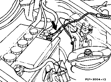
4 Connect up second connector lead of the compression tester to positive terminal
(terminal 30) of the battery.
P01-2004-13

Model 202
5 Open cover (1) on plug connection, terminal 30Z (X4/22) on left wheelhouse.
Connect terminal for compressor recorder (A) to plug connection (X4/22).
Model 202
P01.10-0202-01

6 Disconnect plug from engine/body plug connection (X26/25). Connect adapter lead (01) to pin A1 (arrow) in connection (X26/25). Connect adapter lead (01) with lead (02) to connector (B) for compression recorder.
P01.10-0015-01
Model 210
7 See Cranking engine with starter model 210 (01-011).

8 Mark poly V-belt with chalk at a clearly visible point (arrow).
9 Turn engine in increments and check poly V-belt for damage.
Complete process when marking is visible again (one complete belt revolution).
P13-0025-13
B. Tensioner

The following parts are to be checked on the tension lever bearing (1st version up to 10/85):
9 Check bearing pin (30) of tension lever (360) for firm seating.
Note
The collar of bearing pin (30) must contact the timing case cover (28). The idler pulley must not exhibit any alignment faults.
10 Check tensioner with bearing bush.
Note
The idler pulley must not exhibit any alignment faults. The bearing bushes are worn when there is a detectable play between the bearing pin (30) and tension lever (360).
P13-0059-15
Documenti citati
- ar0110p0110b Rotazione del motore con motorino di avviamento
- ar1325p3200hw Smontare, montare il dispositivo tendicinghia della cinghia trapezoidale
- ra05006010310x
- ra0500601pr03x
- ra1300601pr03x
- ra1300601ta03x
- ra1800601pr03x