Function requirements for thermal management, general points
Circuit 87M (Engine management ON)
Engine runs
Thermal management, general
The coolant temperature of the engine is regulated with the thermal management controlled by the ME-SFI [ME] control unit (N3/10). The following advantages arise from this:
Rapid reaching of the optimal operating temperature
Reduction of the exhaust emissions
Fuel savings
Improved heating comfort
The controlling of the thermal management is dependent on the following sensors and signals:
Coolant temperature sensor (B11/4)
Charge air temperature sensor upstream of throttle valve (B17/7)
Charge air temperature sensor downstream of throttle valve (B17/9)
Pressure sensor downstream of throttle valve (B28/7), engine load
Accelerator pedal sensor (B37), accelerator pedal actuation ( driver type quiet or sporty)
Crankshaft Hall sensor (B70) (with rotational recognition), engine rpm
Temperature sensor in the ME-SFI [ME] control unit
Front SAM control unit (N10/6), outside temperature via interior CAN (CAN B), electronic ignition lock control unit (N73), chassis FlexRay (Flex E), powertrain control unit (N127) and drive train CAN (CAN C1)
Climate control unit (N22/1), status of A/C via the interior CAN (CAN B), electronic ignition lock control unit (N73), chassis FlexRay (Flex E), powertrain control unit (N127) and drive train CAN (CAN C1)
IC (A1), vehicle speed via the user interface CAN (CAN HMI), electronic ignition lock control unit, chassis FlexRay, powertrain control unit and drive train CAN
Electronic Stability Program control unit (N30/4), wheel speed via the chassis FlexRay, powertrain control unit and drive train CAN
Fully integrated transmission control unit (Y3/8n4), status of transmission oil temperature via drive train CAN
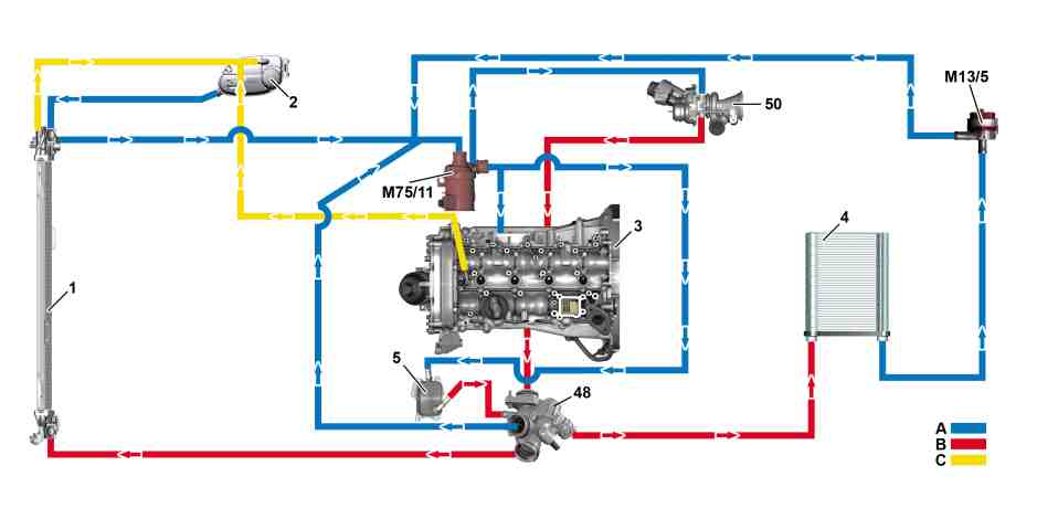
P20.00-2505-79
Schematic diagram |
1 | Engine radiator | 5 | Engine oil/coolant heat exchanger | A | Coolant return to engine | ||
2 | Coolant expansion reservoir | 48 | Coolant thermostat | B | Coolant feed | ||
3 | Engine 274 | 50 | Turbocharger | C | Coolant circuit ventilation | ||
4 | Heating system heat exchanger | M75/11 | Electric coolant pump |
Function sequence for thermal management
The thermal management is described in the following points:
Function sequence for post-start phase with electric coolant pump
Function sequence for coolant thermostat regulation
Function sequence for overheating protection
Function sequence for fan control
Function sequence for radiator trim flaps with (code 5U3 (AIRPANEL))
Function sequence for charge air cooling
Function sequence for post-start phase with electric coolant pump
In the post-start phase the coolant circulation has an open circuit through cutout of the electric coolant pump. Here the electric coolant pump is not actuated by the ME-SFI [ME] control unit. Due to missing cooling the engine warms quicker and the exhaust emission are reduced.
The electric coolant pump is switched off for a cold start if the following conditions are fulfilled:
The coolant temperature lies below 75°C.
No "Heating" was requested by the climate control control unit.
Based on the ''heat'' request, the electric coolant pump switches on and as a result the vehicle interior is heated quickly.

View of electric coolant pump |
M75/11 | Electric coolant pump |
A | Coolant inlet |
B | Coolant outlet |
C | Electric plug connection |
P20.10-2399-05
If the conditions for shutoff of the electric coolant pump are no longer fulfilled, the ME-SFI [ME] control unit stops actuation of the electric coolant pump. The electric coolant pump is therefore switched on and the coolant circulation is achieved again.
Function sequence for coolant thermostat regulation
Opening and closing of the ball rotary slide in the coolant thermostat occurs through the temperature-influenced elongation or contraction of the expansion wax element in a temperature range of about 98°C up to 108°C.
Additionally opening and closing of the coolant thermostat is performed variably and dependent on the motor requests dependent on actuation of the coolant thermostat heating element (R48) .
To do this the ME-SFI [ME] control unit actuates coolant thermostat heating element by means of a ground signal dependent on the operating conditions . The power supply takers place over "circuit 87 M2".
The coolant thermostat can take on the following positions:
Closed
Open (mixed-fuel mode)
Open (cooler operation)
Closed
The ball rotary slide of the coolant thermostat is closed if the following conditions are fulfilled:
Coolant temperature below about 98°C
Coolant thermostat heating element deenergized
No wide open throttle request
In this position the coolant flows through the engine circuit and the heater heat exchanger as required. The engine radiator is not integrated in the coolant circuit. The coolant is heated more quickly in this way.
Through rapid warming the engine reaches its operating temperature quicker which is favorable for fuel consumption and emissions.
Open (mixed-fuel mode)
The ball rotary slide begins to open if one of the following conditions is fulfilled:
Reaching a coolant temperature of approx. 98°C for the first time after starting (no full-load request)
Coolant thermostat heating element is energized
In a temperature range of the coolant of about 98°C up to 108°C or according to energization of the coolant thermostat heating element, the expanding wax element begins to expand and actuates the ball rotary valve. This releases the connection tr the engine radiator. The opening cross-section of the ball rotary slide is adapted according to the temperature of the expanding wax element or the coolant temperature. In this way the volumetric flow rate of coolant to the engine radiator can be varied.

View of coolant thermostat closed |
48 | Coolant thermostat housing |
48a | Expanding wax element |
48b | Ball rotary slide |
R48 | Coolant thermostat heating element |
A | From engine |
B | To engine radiator |
C | To heater heat exchanger |
P20.10-2324-76
Open (cooler operation)
For exceeding of a coolant temperature of about 108°C the ball rotary slide is opened completely and the coolant can flow unheeded over the engine radiator.
For a coolant temperature > 85°C and an open circuit request the ball rotary slide also opens through heating of the expanding wax element fully.
The coolant temperature is lowered under the following conditions to prevent a critical temperature range arising:
Intake air temperature > 38°C
engine speed > 3000 rpm
Engine load > 30%
The coolant temperature is lowered dependent on the outside temperature through heating of the expanding wax element (for an outside temperature < 12°C to about 90°C and for an outside temperature > 12°C to about 80°C).

View of the coolant thermostat opened |
48 | Coolant thermostat housing |
48a | Expanding wax element |
48b | Ball rotary slide |
R48 | Coolant thermostat heating element |
A | From engine |
B | To engine radiator |
C | To heater heat exchanger |
P20.10-2325-76
Function sequence for overheating protection
In a case of thermal overload the overheating protection protects the catalytic converters against engine damage and overheating damage.
The following measures are taken for overheating protection:
A characteristics map dependent ignition angle setting in the direction "retard", dependent on the engine load and rotational speed, as of a coolant temperature of about 90°C and a charge air temperature of about 20°C
Reduced opening of the throttle valve actuator (M16/6), dependent on the engine load and speed
Shortening of the injection period of the fuel injectors (Y761 to Y764) according to the lower air mass
Actuation of the coolant thermostat heating element by the ME-SFI [ME] control unit for full opening of the ball rotary slide in the coolant thermostat
A warning message in the instrument cluster is shown for an excessively high coolant temperature. To do this the ME-SFI [ME] control unit sends an appropriate signal via the drive train CAN to the powertrain control unit, chassis-FlexRay and electronic ignition lock control unit via the user interface-CAN (CAN HMI) to the IC.
The powertrain control unit reads in the temperature in the low-temperature circuit via the low-temperature circuit temperature sensor (B10/13). In this way the coolant temperature in the low-temperature circuit is detected.
Function sequence for fan control
The powertrain control unit actuates the fan motor (M4/7). Here the actuation occurs via the drivetrain-LIN (LIN C3) and all rotational speeds between 0 and 100% can be adjusted. For faulty actuation the fan motor rotates at its maximum rotational speed (fan emergency mode).
The climate control control unit transmits the status of the A/C to the interior CAN over the electronic ignition lock control unit, the chassis-FlexRay to the powertrain control unit and via the drive train CAN to the ME-SFI [ME] control unit.
Delayed fan switch off
The fan motor runs on for "ignition OFF" for up to 6 minutes if the coolant temperature or the engine oil temperature has exceeded the prescribed maximum values. If the battery voltage drops down a lot, the delayed fan switch off is suppressed.
Function sequence for radiator trim flaps with (code 5U3 (AIRPANEL))
The radiator trim flaps are close in order to lower the fuel consumption (thorough having a lower aerodynamic drag). This also causes reduced engine compartment cooling off and a dampening of engine external noise emissions to the outside. The radiator trim flaps are opened under the following preconditions:
Coolant temperature > 105 °C
Charge air temperature > 34°C
Vehicle speed > 180 km/h
Fan output > 30%
The radiator trim flap actuator motor (M2/37) is actuated by the powertrain control unit via the drivetrain-LIN . The radiator trim flaps are closed when the conditions are no longer fulfilled or the engine is off.
Through the spring preload of the actuator motor, the radiator trim flaps are opened suddenly with a noticeable noise if a malfunction occurs (emergency function).
Cleaning position
Turn the key in the ignition lock to position 2 (engine not have started). The radiator trim flap opens itself after about 120 s.
Function sequence for charge air cooling
The charge air cooler is connected to the low-temperature circuit. If the charge air temperature is > 35°C, the low-temperature circuit circulation pump 1 (M43/6) is actuated by the powertrain control unit and via drivetrain LIN. If the charge air temperature falls below 25°C, the low-temperature circuit circulation pump 1 is switched off again.
The charge air temperature is detected in the charge air distributor by the charge air temperature sensor upstream of the throttle valve and the charge air temperature sensor downstream of the throttle valve and sent to the CDI control unit using a voltage signal.
In the low-temperature circuit the temperature control of the charge air cooler takes place over the low-temperature circuit switchover valve (Y73/1). According to ambient conditions the charge air cooler is regulated over the coolant quantity in the low-temperature circuit through the low-temperature circuit switchover valve. The low temperature circuit switchover valve receives the actuation for this from the powertrain control unit via drivetrain LIN. Feedback of the position from the low-temperature circuit switchover valve takes place via the drivetrain LIN to the powertrain control unit.
Only open the cap on the low-temperature circuit when the charge air temperature is increased (lack of power) and the engine is cold. The coolant must reach up to the cap.