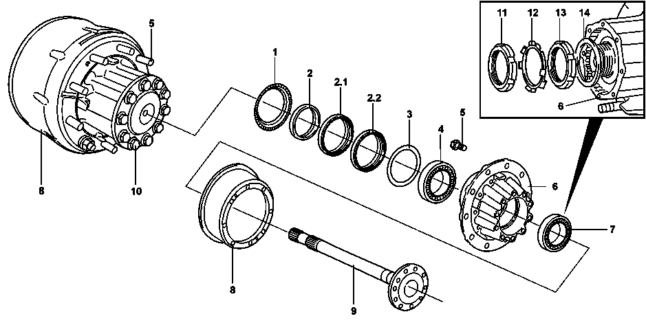
B35.20-0060-09
4 | Inner taper roller bearing | 10 | Bolt | ||||
1 | ABS measuring ring | 5 | Wheel fastening bolt | 11 | Outer grooved nut | ||
2 | snap ring | 6 | Wheel hub | 12 | Locking plate | ||
2.1 | Radial seal | 7 | Outer taper roller bearing | 13 | Inner grooved nut | ||
2.2 | Inner sealing ring | 8 | Brake drum | 14 | Spacer washer | ||
3 | Cover plate | 9 | Semi-shaft |
| Remove | ||
Notes on evaluating leakages | |||
1 | Remove the brake drum (8) |
| |
Mark the assembly position of the brake drum (8) with regard to the wheel hub (6). | |||
2 | Mechanically lock the differential lock | ||
3 | Remove the ABS sensor |
| |
4 | Remove the bolts (10) and lift out the axle shaft (9) | ||
5 | Unlock and remove the outer slotted nut (11) | Claw-type wrench | |
6 | Remove the locking plate (12) and remove the inner slotted nut (13) with the spacer disk (14) | Claw-type wrench | |
7 | Remove the external tapered roller bearing (7), and remove the wheel hub (6) | Removal and installation tool | |
8 | Remove the ABS measuring ring (1) | ||
9 | Remove the radial shaft sealing ring (2.1) and the inner sealing ring (2.2) | ||
10 | Remove the cover plate (3) and remove the inner tapered roller bearing (4) | ||
11 | Remove the thrust ring (2) | Use a appropriate tool to remove the thrust ring (2). | |
| Install | ||
12 | Clean the contact surface on the axle and the wheel hub (6) | ||
Warning | Risk of injury. Skin or eye injuries may result when handling hot or glowing objects. | Wear protective gloves, protective clothing and safety glasses, if necessary. | |
13 | Heat the thrust ring (2) to approx. 80°C and install up to the top on the axle tube | Press the thrust ring (2) touching the axle tube until it cools. | |
14 | Install the inner tapered roller bearings (4) on the wheel hub (6) | Slightly grease the inner tapered roller bearing (4). | |
MB multipurpose grease, 400 g | |||
15 | Install a new cover plate (3) on the wheel hub (6) | ||
16 | Install the inner sealing ring (2.2) and the radial shaft sealing ring (2.1) | | |
Slightly grease the outer sealing surface of the inner thrust ring (2.2). | |||
MB multipurpose grease, 400 g | |||
Drift | |||
Supplementary set | |||
17 | Install the ABS measurement ring (1) on the wheel hub (6) | Drift | |
18 | Install the wheel hub (6) on the rear axle | Removal and installation tool | |
19 | Install the outer tapered roller bearings (7) on the wheel hub (6) | Slightly grease the outer tapered roller bearing (7). | |
MB multipurpose grease, 400 g | |||
20 | Install the spacer disk (14) with the inner slotted nut (13) | Meanwhile, rotate the wheel hub (6) some times, applying a cross-shaped rubber hammer on the rear wheel hub (6). | |
.Internal and external grooved nut | |||
Claw-type wrench | |||
21 | Loosen the inner slotted nut (13) again at approx. 1/4 of one turn | Claw-type wrench | |
22 | Check the clearance of the wheel hub (6) tapered roller bearings (4, 7) | ||
.Axial clearance of wheel hub bearings | |||
Dial indicator holder | |||
Dial gage | |||
Claw-type wrench | |||
23 | Oil the locking plate (12) and install in the rear axle | Installation: The inner flap of the locking plate (12) must be installed facing outwards. | |
24 | Install and tighten the outer slotted nut (11) | .Internal and external grooved nut | |
Claw-type wrench | |||
25 | Recheck the clearance of the wheel hub (6) tapered roller bearings (4, 7) |
| |
.Axial clearance of wheel hub bearings | |||
Dial indicator holder | |||
Dial gage | |||
Claw-type wrench | |||
26 | Lock the outer slotted nut (11) | Bend the locking plate locks (12) in the appropriate grooves in the inner slotted nut (13) and the outer slotted nut (11). | |
27 | Clean the sealing surface of the wheel hub (6) and the axle shaft flange (9) and apply sealant | Omnifit sealantFD10-1042 | |
28 | Install the axle shaft (9) with new screws (10) | .Rear axle shaft screw at the wheel hub | |
29 | Install the ABS sensor |
| |
30 | Mechanically unlock the differential lock | ||
31 | Install the brake drum (8) |
| |
Install the brake drum (8) in the assembly position indicated in relation to the wheel hub (6). |


740 589 01 15 00
Drift
748 589 00 07 00
Claw-type wrench
001 589 53 21 00
Dial gage
363 589 02 21 00
Dial indicator holder


055 589 09 61 00
Removal and installation tool
748 589 00 63 00
Supplementary set
748 589 04 15 00
Drift
Documenti citati
- ah0000n001101a Avvertenze per la valutazione di difetti di tenuta
- ar3520b031006te
- ar3540b0701a
- ar4210b1010ta
- ar4210b1010ta
- ar4230b0150d
- as0000z000201a Pericolo di lesioni alla pelle e agli occhi nel maneggiare oggetti caldi o incandescenti