
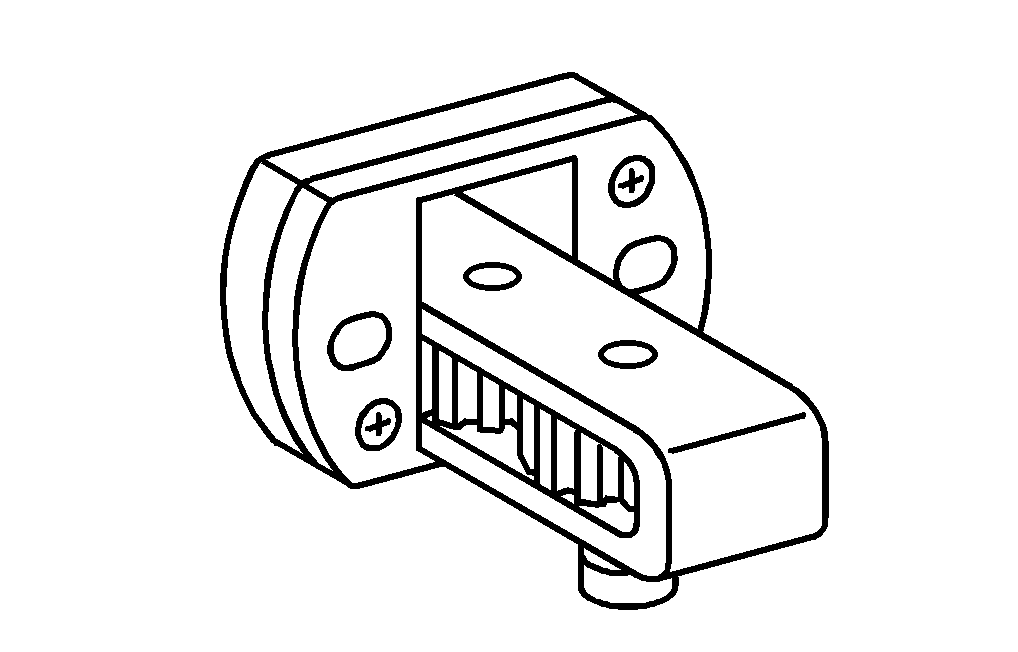
000 589 88 33 00
Puller, two-arm
904 589 04 63 00
Turning device

Remove
1 | Install the turning device (1) on the timing case. |
Only with the gearbox installed. |
W26.45-1280-01

2 | Place the marking (arrow) on the input shaft of the power take-off in relative position of "10 o'clock". |
With the gearbox installed, spin the engine using the turning device; if the transmission is removed, spin the input shaft. |
W26.45-1278-01

3 | Remove the input shaft of the power take-off (2) with the bearing (5) and the cover of the oil pump (3). |
4 | Remove the cover of the oil pump (3) and the O-Ring (4) from the input shaft of the power take-off (2). |
5 | Remove the retaining ring (6) and detach the bearing (5) with the puller from the input shaft of the power take-off (2). |
Install
6 | Install the cover of the oil pump (3) and a new O-Ring (4). |
The markings (arrows) on the oil pump cover (3) and on the housing must coincide. |
7 | Heat up the bearing (5) up to 80 °C, install it on the input shaft of the power take-off (2) and lock it with the retaining ring (6). |
8 | Install the input shaft of the power take-off (2). |
The markings (arrows) on the input shaft of the power take-off (2) must be placed in the relative position of “10 o'clock”. |
W26.45-1279-11
Documenti citati
- as0000z000201a Pericolo di lesioni alla pelle e agli occhi nel maneggiare oggetti caldi o incandescenti