
King-pins |
Example |
B33.25-0061-02


Brake shoe activation shaft (drum brake) |
Front and rear axle - right and left | |
Example |
B42.15-0022-01
B42.10-0471-01

Mechanical brake lash adjuster |
Example - OF |
B42.10-0472-01


B46.40-0012-01
Intermediate steering arm | ||||
Example - O 371; O 400 and Platforms | ||||
Intermediate steering arm | ||||
Example - OF; OH and OH-L | ||||
B46.40-0015-01


B46.00-0016-01
Chassis 664.238 - Special execution 8X2 First Pitman arm set | ||||
Chassis 664.238 - Special execution 8X2 Second Pitman arm set | ||||
B46.00-0017-01

Door activation mechanism - Complete bus |
B72.10-0018-01


Spring pins |
Front and rear - Example - OF |
B32.25-0002-01
B32.30-0001-01

Stabilizer arm |
Front and rear - Example - OF and OH |
B32.20-0045-01


Universal joints, sliding sleeve and intermediate bearing |
Example - OF and OH |
B41.10-0026-01
B41.10-0027-01

Universal joints and sliding sleeve |
Exemplo - O 371, O 400 e Plataformas |
B41.10-0025-01
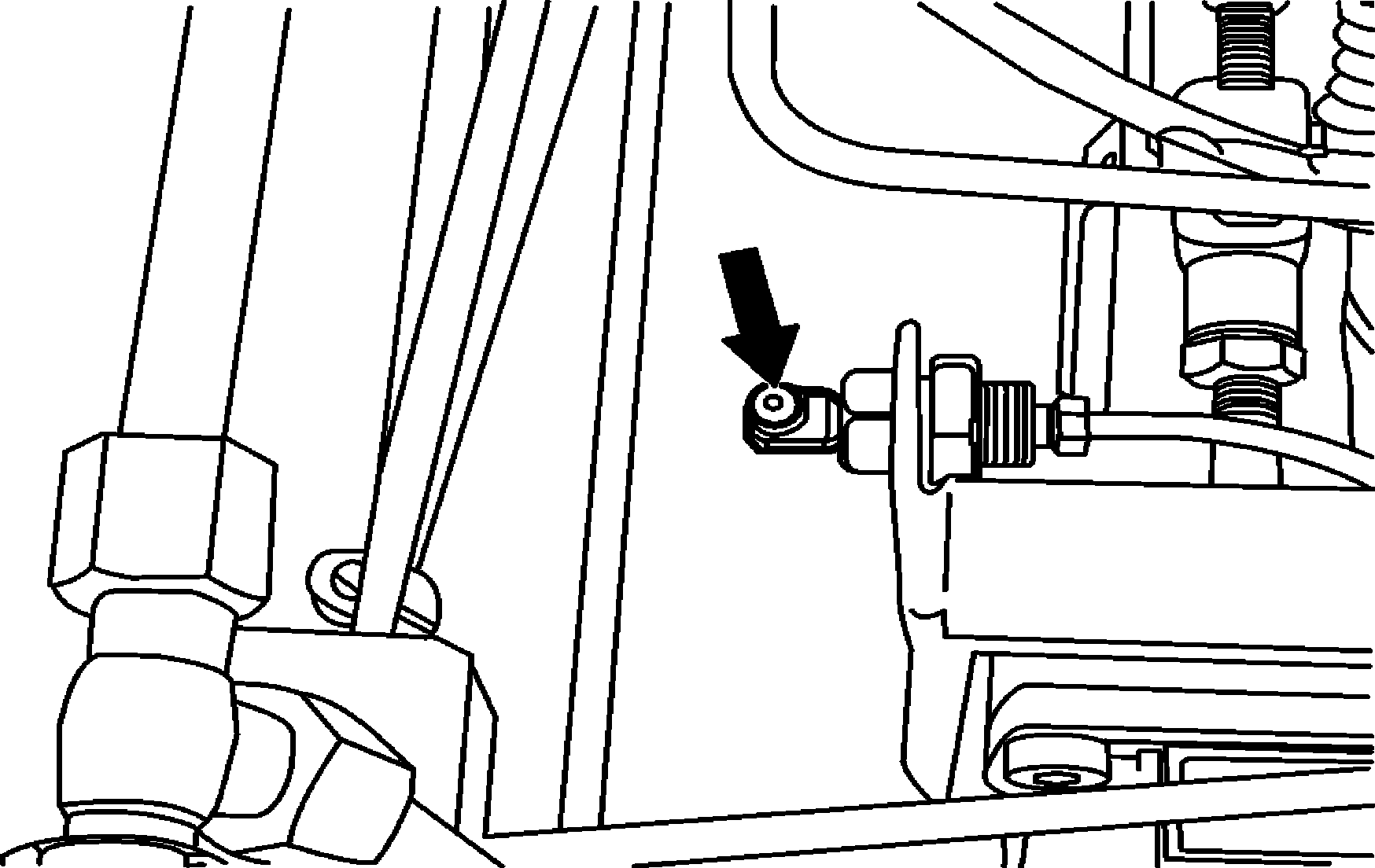
Pedals shaft |
Example - O 371, O 400 and Platforms |
B29.10-0020-01

Acceleration mechanism shaft |
Not valid for vehicles with electronic engine management | |
Several points located along the accelerator rod | |
Example - O 371; O 400 and Platforms |
B30.10-0001-01

Engine acceleration and shutoff mechanism shaft |
Not valid for vehicles with electronic engine management | |
Example - O 371; O 400 and Platforms |
B30.10-0002-01


B30.10-0004-01
B30.10-0006-01
B30.10-0005-01
Acceleration mechanism shaft |
Example - OHL |
Acceleration mechanism shaft |
Example - OF |
Acceleration mechanism shaft |
Vehicles with automatic transmission |

Fan belt stretcher pulley shaft |
Valid only for 0 371 (Example) |
B20.40-0007-01

Fan belts stretcher and pulleys |
Valid for O 400 and OH-L (Example) |
B20.40-0008-01


B26.10-0006-01
Bearing sliding and pads | ||||
Example - O 371; O 400; OH-L | ||||
Control lever's tower | ||||
Example - OF | ||||
B26.10-0007-01


B30.10-0003-01
Bearings and rods of the displacement areas | ||||
Example - O 371; O 400 and Platforms | ||||
Bearings and rods of the displacement areas | ||||
Example - OF | ||||
B30.10-0007-01

Engine brake spherical end piece |
B14.10-0016-01

Additional steered rear axle RL 75 EC |
Valid for the Capachassis |
B35.50-0021-01
1 | Clean grease fittings using cloth | ||
2 | Oil the lubrication points | When utilizing high pressure lubrication pumps, the lubricating pressure should not exceed 180 bar. | |
A lubrication point is considered well lubricated when new grease is shown at its contour. | |||
To ensure a good shaft end lubrication it is recommended to lift vehicle using front axle. | |||
3 | Clean exceeding grease | ||
4 | Lubricate with manually applied grease | Lubricate the articulations, rods, hinges, locks, ball joints, cables and bearings. | |
To correctly lubricate the ball joints it is necessary to remove the lock (when present) and disengage the universal joint. Fill the universal joint with grease and engage it again. Next, install the lock. | |||
At the bearings and pads area, insert the lubricating nozzle under the protection rubber (when present) and apply grease in the bearing and pads displacement area. |