33 - 8564.01 Disassembly and assembly of ring gear with differential
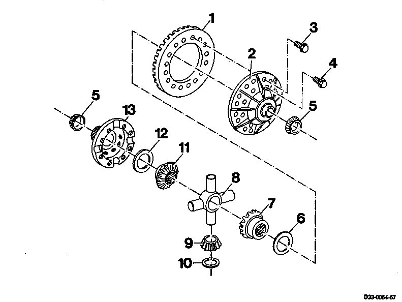
1 Ring gear check, replace only together with drive pinion
2 Differential housing
3 Bolt replace M10x1 12.9 95...105 Nm
4 Bolt replace M10 12.9 90...100 Nm
5 Tapered roller bearing check
6 Thrust washer check
7 Axle shaft gear check
8 Differential spider check
9 Differential pinion check
10 Thrust ring check
11 Axle shaft gear check
12 Thrust washer check
13 Differential housing cover
Adjustment values |
Friction torque in differential Nm 30...50 |
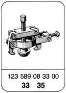


Special tools

Disassembly
1 Pull both tapered roller bearings off of differential with special tool .
123 589 08 33 00

2 Place differential on mounting jig and screw off ring gear. The ring gear can be knocked off of the differential by tapping lightly around the circumference.
337 589 02 31 00

3 Screw off differential housing cover and remove.
4 Remove top front axle shaft gear and thrust washer.
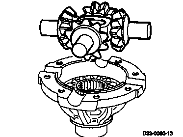
5 Remove differential spider with differential pinions and spherical washers.

6 Remove differential pinions with spherical washers from differential spider.
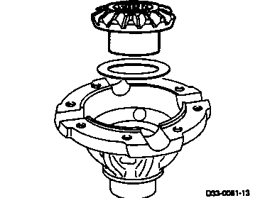
7 Remove bottom front axle shaft gear with thrust washer.
8 Clean all parts and check for wear.

Assembly
1 Install thrust washer on front axle shaft gear.
Note
The lubricating groove on the thrust washer should point toward the front axle shaft gear.
2 Install front axle shaft gear in differential housing.
3 Slide differential pinions with spherical washers onto differential spider.
4 Install complete differential spider in cover.
5 Position thrust washer on other front axle shaft gear and install together with differential spider.
Note
The lubrication groove in the thrust washer should point toward the front axle shaft gear.

6 Position differential housing and clamp.
Note
Markings (same numbers) must coincide.
337 589 02 31 00

7 Tighten differential housing (90...100 Nm).

8 Check turning torque for differential and adjust (30...50 Nm).
Note
The turning torque can be changed with the thrust washers (front axle shaft gear). The thrust washers are available in thicknesses from 1.30...1.85 mm in increments of 0.05 mm.
741 589 00 15 00
9 Install ring gear and tighten.
(95...105 Nm)
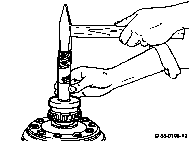
10 Heat both tapered roller bearings up to ap-
prox. 80 °C and drive on.

11 The tapered roller bearings should contact the differential housing without play. Check with feeler gauge.
Referenced documents
- ra3312d000200x 0002 - Installation overview Front axle AL 1/5, 1/6 (model 730.350/351) Models 667, 668, 669, 670
- ra3312d000300x 0003 - Cross-section Front axle AL 1/5, 1/6 (model 730.350/351) Models 667, 668, 669, 670
- ra3312d000400x 0400 - Special tools Front axle AL 1/5, 1/6 (model 730.350/351) Models 667, 668, 669, 670
- ra3312d000500x 0005 - Technical data Front axle AL 1/5, 1/6 (model 730.350/351) Models 667, 668, 669, 670
- ra3312d000900x 0009 - Important repair information Front axle AL 1/5, 1/6 (model 730.350/351) Models 667, 668, 669, 670