GF46.20-B-2002B | Single-circuit power steering in left steer, function | 12.02.16 |
Steering gear 765.810
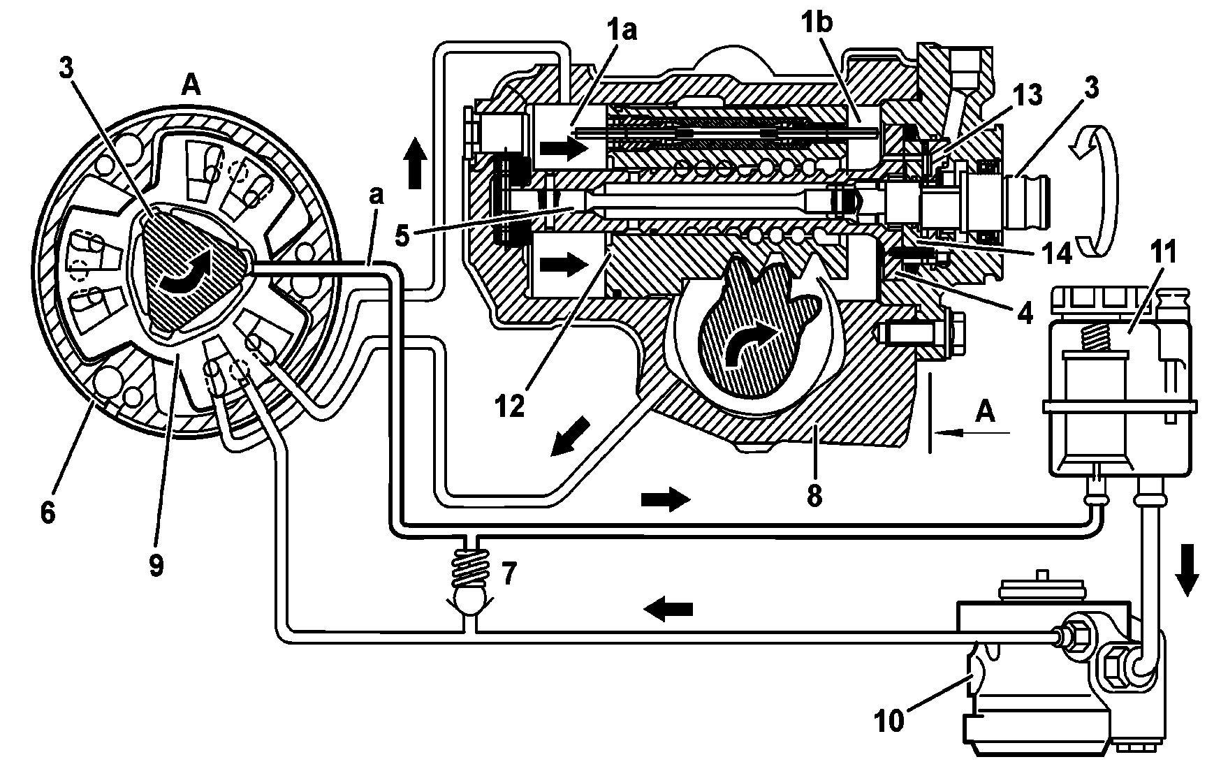
B46.20-0041-05
Hydraulic steering diagram of a circuit when turning left (left side steering gear)
1a, 1b Stroke limiting valve
3 Primary shaft
4 Steering worm
5 Torque bar
6 Star valve
7 Pressure relief valve
8 Steering gear
9 Rotor
10 Steering hydraulic pump
11 Hydraulic oil reservoir
12 Power piston
13 Distribution cover - below
14 Distribution cover - above
A Star valve sectioning
a Return groove

B46.20-0038-04
Stroke limiting valve in driving position to the left (left side steering gear)
1a, 1b Stroke limiting valve
12 Power piston
A Lower work chamber
B Upper work chamber
Operation
When turning the steering wheel to the left, the power piston (12) with thread from the balls system recirculating to the left (steering to the left) is mechanically displaced to the upper work chamber (B).
The power piston (12) mechanical displacement is hydraulically balanced pushing oil to the lower work chamber (A).
At the steering wheel rotation transmission to the primary shaft (3) or vice-versa, the steering gear (8) torque bar (5) deforms elastically (torque), so that there is relative movement between the rotor (9) and the distribution covers (13, 14). This way, rotor distribution edges (9) suffer an offset from the central position (neutral) in relation to the distribution covers (13, 14) distribution edges.
When turning the steering wheel to the left (steering to the left), oil distribution flow to the lower work chamber (A) opens according to the steering wheel rotation degree and allows oil flow to the lower chamber.
At the same time, oil return flow to the lower work chamber (A) is reduced or closed according to the steering wheel rotation degree, generating the necessary pressure to the lower chamber.
The oil to the upper work chamber (B) is driven by the power piston (12) movement, for the oil return flow from the upper work chamber and flows through the oil return pipe to the hydraulic power steering (11) reservoir.
The pressure generated at the lower work chamber (A) acting on the power piston (12) provides steering wheel hydraulic assistance. When moving the piston to the upper work chamber (B), (turning to the left - steering wheel to the left), the stroke limiting valve (1b) is engaged at the moment it touches the upper stop, in other words, at the valves case, allowing oil flow from the lower work chamber (A) to the upper work chamber (B) and to the oil return pipe through the star valve (6). Oil pressure at the lower work chamber (A) reduces accordingly.
Referenced documents
- gf4620b2103c Pressure reduction valve, location/task/design/function