S08.00-A021-79
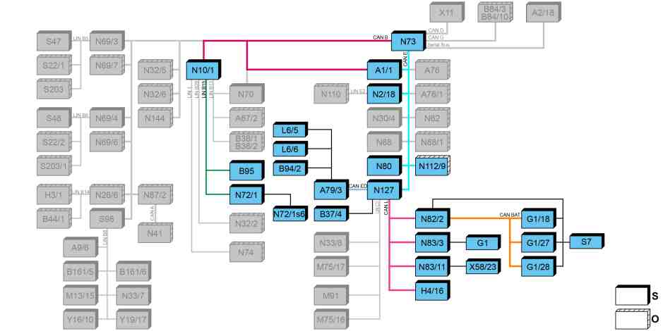
Block diagram |
A1/1 | Instrument cluster (KI) control unit | N80 | Steering column tube module (MRM) control unit | |
A79/3 | Electric machine control unit | N82/2 | Battery management system control unit | |
B94/2 | Electric machine temperature sensor | N83/3 | DC/DC converter control unit | |
B95 | Battery sensor | N83/11 | Alternating current charger for high-voltage battery | |
B37/4 | Accelerator pedal module | N112/9 | HERMES control unit (with code JH3 (Communication module (LTE) for digital services)) | |
G1 | On-board electrical system battery | N127 | Drivetrain control unit | |
G1/18 | High-voltage battery 1 | S7 | High-voltage disconnect device | |
G1/27 | High-voltage battery 2 | X58/23 | 230 V feed socket | |
G1/28 | High-voltage battery 3 | CAN B | Interior CAN | |
H4/16 | Sound generator | CAN BAT | Battery management system CAN | |
L6/5 | Left electric machine rpm sensor | CAN E | Chassis CAN | |
L6/6 | Right electric machine rpm sensor | CAN ED | Electric drive system CAN | |
N2/18 | Supplemental restraint system (SRS) control unit | CAN L | Hybrid CAN | |
N10/1 | Signal acquisition and actuation module (SAM) control unit | LIN B15 | Battery sensor LIN | |
N72/1 | Upper control panel (UCP [OBF]) control unit | O | Optional | |
N72/1s6 | Transmission mode button | S | Default | |
N73 | Electronic ignition lock (EZS) control unit |
High-voltage on-board electrical system energy management in general
High-voltage on-board electrical system energy management manages the provision (supply) and consumption (balance) of electrical energy. The goal is a low energy consumption and an optimal charging process.
The 12 Von-board electrical system is supplied by the DC/DC converter control unit (N83/3), which works here like an alternator in a conventional combustion engine vehicle.
The energy management function is integrated in the powertrain control unit (N127).
The following components are extensively involved in high-voltage on-board electrical system energy management:
Electric machine
High-voltage batteries
Battery management system control unit
Alternating current charger for high-voltage battery
Drivetrain control unit
Electric machine control unit
230 V feed socket
In detail the energy management encompasses the following functions:
Vehicle network support
Switching on and disconnecting the high-voltage on-board electrical system
Interlock circuit
Insulation monitoring
Energy distribution
Drive programs "C", "E", "E+"
Vehicle network support
All implemented control units are supplied via the on-board electrical system battery (G1) of the 12 V on-board electrical system. The on-board electrical system battery sits in the seat base of the front passenger seat. When the vehicle is stationary and the ignition is not switched on, all consumers are supplied by the on-board electrical system battery.
On-board electrical system support ensures that the on-board electrical system battery is charged at all times. If the charge level of the on-board electrical system battery or the outside temperature during operating status do not reach a threshold value, they are supercharged via the DC/DC converter control unit (N83/3). The DC/DC converter control unit converts the high voltage from the high-voltage on-board electrical system to the voltage level of the 12 V on-board electrical system to supply the 12 V consumers and to charge the on-board electrical system battery. To do this the DC/DC converter control unit receives a voltage specification for the 12 V on-board electrical system from the signal acquisition and actuation module (SAM) control unit (N10/1).
After the ignition has been switched on, the available voltage of the on-board electrical system battery is checked and, as required, supercharged and supported via the DC/DC converter control unit by the high-voltage batteries (G1/18, G1/27, G1/28). The consumers of the 12 V on-board electrical system continue to be supplied by the on-board electrical system battery.
If the charge level of the on-board electrical system battery or outside temperature during operating status do not reach a threshold value, a cut-in of the high-voltage on-board electrical system takes place, even after prior testing, to support and, if necessary, charge the 12 Von-board electrical system, including the on-board electrical system battery.
By connecting the charging cable to the 230 V feed socket (X58/23) and to the private power network (stationary service line) or a public power network (charging station), the high-voltage batteries are supercharged externally.
Switching on and disconnecting the high-voltage on-board electrical system
Depending on the driving condition, e.g. charging, service, or accident, the high-voltage on-board electrical system can and must be switched on or disconnected. For this purpose, the high-voltage output of the high-voltage batteries can be disconnected from the high-voltage on-board electrical system by contactors actuated by the powertrain control unit.
In the event of an accident, a security system recognizes the severity of the crash and decides whether the high-voltage on-board electrical system must be switched off reversibly or irreversibly.
Reversible: A small amount of minor damage without triggering the airbag or impairing the high-voltage on-board electrical system. The high voltage buffer is discharged within a few seconds. The vehicle can be re-started via the ignition.
Irreversible: The power supply of the contactors is interrupted by a pyrotechnical element. The high voltage buffer is discharged within a few seconds. The vehicle cannot be started again by the operator.
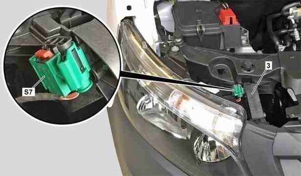
High-voltage disconnect device (Service Disconnect) |
3 | Module bracket |
S7 | High-voltage disconnect device |
S08.00-A022-75
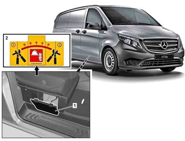
Alternative high-voltage disconnect device for an emergency (rescue separation point) |
1 | Seat base flap of front passenger seat |
2 | Information label (with electric line) |
S08.00-A015-76
Manual power disconnect of high-voltage on-board electrical system
Two high-voltage disconnect devices are available:
High-voltage disconnect device (Service Disconnect):
The high-voltage disconnect device (S7) in the engine compartment serves the workshop for the vehicle power disable process.
It is located in the load line of the contactors, is connected in series, and can be removed for service. The high-voltage disconnect device is located on the front right module bracket (3) in the engine compartment.
Alternative high-voltage disconnect device for an emergency (rescue separation point):
The alternative high-voltage disconnect device is located in the seat base of the front passenger seat. It is identified with an information label (2). During this process, it is necessary to cut through the electric line at the marked separating point. The electric line is not located in the high-voltage on-board electrical system.
The standardized rescue separation point serves the emergency workers through irreversible shutoff of the high-voltage on-board electrical system during rescue and recovery operations.
The alternative high-voltage disconnect device must be actuated only if the high voltage disconnect device (Service Disconnect) cannot be actuated in the engine compartment because this step is irreversible.
For the rescue services, there are two special adhesive labels with the QR Code® as a link to the rescue card. It is located on the interior of the vehicle socket flap as well as on the B-pillar on the front passenger side. They mark the position of the components of the high-voltage on-board electrical system as well as the pyrotechnical equipment and disconnect devices.
Interlock circuit
If the interlock circuit is interrupted, e.g. by disconnecting a connector coupling, this leads to opening of the contactors in the high-voltage batteries due to interruption of the power supply. Contactor opening leads to power-down of the high-voltage on-board electrical system.
Active rapid discharge is also integrated in the high-voltage components, since the high-voltage on-board electrical system is not de-energized immediately after opening the contactors due to capacitors in the high-voltage components.
If the interlock circuit is interrupted during operating status, the shutoff of the high-voltage on-board electrical system takes place only after the next vehicle stop if the selector lever is set to position "N" at vehicle stillstand or the key is turned to the "OFF" position.
To be able to perform service work without any hazard due to electric shock, the high-voltage on-board electrical system's voltage must also be switched off. For this purpose, the front right high-voltage disconnect device (S7) in the engine compartment can be actuated; this results in the interlock circuit also being interrupted.
Insulation monitoring
Insulation faults in the high-voltage on-board electrical system are detected early on due to the high-voltage components' insulation monitoring. A sensor is integrated in each high-voltage battery and constantly measures the resistance. The measured value is transmitted via the hybrid CAN (CAN L) by the battery management system control unit (N82/2) to the powertrain control unit and is evaluated there. If a certain resistance value is not reached, neither charging of the high-voltage batteries nor operating status is possible.
Energy distribution
The operation strategy in the vehicle is designed to control the flow of energy dynamically. Therefore the necessary energy is prepared for the arising driving condition in good time. To this much information flows in the intelligent controlling, which evaluates this information and allows the respective drive torques to be provided. Information includes the driver request, the requests on the vehicle and the environmental conditions.
Also the achievable service life of the energy storage system very much depends on the operating strategy. This in particular requires, in a heating case, an intelligent energy management, that uses all available energy sources, in order to increase the range of the vehicle. In this case, the energy distribution to the high voltage components, is limited depending on the current driving situation (12 V on-board electrical system, heating and climate control functions).
Drive programs "C", "E", "E+"
Three drive programs are offered. At the start, the base drive program "E" ("Economy") is active. The two programs "C" ("Comfort") and "E+" ("Economy Plus") can be selected via the drive program button (N72/1s6) in the center console.
The drive program "E+" is designed for driving as economically as possible. This includes limiting the type-related maximum speed, adaptation of the accelerator pedal characteristic as well as fixed setting of the maximum regenerative braking stage.
There is also an acceleration boost as a time-limited function which is triggered by the kickdown functionality of the accelerator pedal.
In Economy mode, the heating or air conditioning switches to an energy saving program.
Further information for this is contained in the separate function description "Elektrofahrzeug Funktion" (Electric vehicle function).
Referenced documents
- gf0800s9999tre Overview of system components for an electrical vehicle
- gf0800s9999tre