Installation instructions
Engine block heater 20.2
Model 201
In order to protect the engine from completely cooling down at low outside temperatures, an electric engine block heater can be installed retroactively in a core hole of the engine block to keep warm or heat up the engine coolant.
The engine block heater is connected to the local electricity network via the existing plug on the unit.
It has a power consumption of 500 W at a voltage of 220 V, or 115 V as an alternative.


Special tools
119 589 00 09 00
001 589 66 21 00
124 589 15 21 00
The installation instructions are subdivided into the following sections:
A. Procedure
a) Models 201.018 (engine 102.91), 201.022/023 (engine 102.92)
201.024 (engine 102.96, 201.028 (engine 102.98)
b) Model 201.029 (engine 103.942)
B. Parts ordering note
A. Procedure
a) Models 201.018 (engine 102.91), 201.022/023 (engine 102.92)
201.024 (engine 102.96, 201.028 (engine 102.98)

P01-2082-13
1 Disconnect ground cable at battery.
2 Remove, install lower engine compartment panelling (RI 01-006).
3 Drain coolant completely (RI 20-010).
4 Unscrew the screw plug (5) on the left of the cylinder block, special tool 119 589 00 09 00.

P20-5230-13
5 Screw engine block heater (1) with O-ring into the cylinder block, tightening torque 70 Nm.

P20-5231-13
6 Route electric cable of engine block heater along the vacuum line and at the existing Omega clamp on the intake manifold to the left wheelhouse and fasten with cable straps (arrows).
Avoid chafing points.

P20-5034-13
7 Drill two 3 mm dia. holes for attaching the retaining spring (13) and cap (12) to the left wheelhouse (see attachment diagram).
Paint holes with zinc-dust paint.
Attachment diagram
12 Cap
13 Retaining spring
14 Screw (B3.9 x 9.5)
15 Washer (A4.3)
8 Connect ground cable at battery.

P20-2143-13
9 Pour in coolant (RI 20-010).
10 Check cooling system for leaks
(RI 20 - 017).
Special tool 124 589 15 21 00.
b) Model 201.029 (engine 103.942)

P20-5066-13
1 Disconnect ground cable at battery.
2 Remove, install lower engine compartment panelling (RI 01-006).
3 Drain coolant completely (RI 20-010).
4 Unscrew the screw plug (b) on the right of the cylinder block.
Special tool 119 589 00 09 00.
5 Screw engine block heater with O-ring into the cylinder block and tighten.
Tightening torque 70 Nm.

P20-5033-13
6 Attach shield (6) above the engine block heater with two hexagon bolts (M615) and two washers.
7 Route electric cable from engine block heater on the right of the cylinder block forwards above the mounting on the engine mounting bracket and fasten with clamps.
The mounting parts on the engine mounting bracket must be assembled in the following sequence:
7 Washer A8.4 (3 mm thick) between engine mounting bracket and clamp
8 Clamp
9 Washer A8.4 (1.5 mm thick)
10 Hexagon bolt (M8 40)
Ensure that the electric cable is as far as possible from the exhaust manifold. Avoid chafing points.
Attachment to engine:
1 Coolant preheater
2 O-ring
3 Clip
4 Washer (A6.4)
5 Hexagon bolt (M6x15)
6 Shield
7 Washer A8.4 (3 mm thick)
8 Clip
9 Washer A8.4 (1.5 mm thick)
10 Hexagon bolt (M8x40)

P20-5032-13
8 Further routing and attachment of electric cable to crankcase and to the alternator mounting bracket with clips and via the main harness of the alternator to the front of the right side member with cable straps (arrows).
Attachment to crankcase and alternator mounting bracket:
8 Clip
9 Washer A8.4 (1.5 mm thick)
11 Hexagon bolt (M8x20)
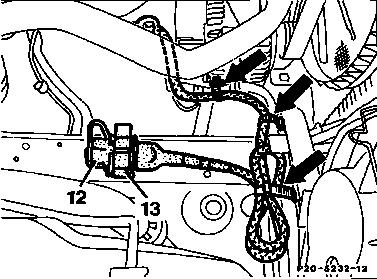
P20-5232-13
Ensure that the electric cable cannot be caught up in the belt drive.
P20-5034-13
9 Screw on retaining spring (13) and cap (12) by drilling two 3 mm dia. holes.
Attachment diagram:
12 Cover
13 Retaining spring
14 Screw (B 3.9x9.5)
15 Washer (A 4.3)
Paint holes with zinc-dust paint.
10 Connect ground cable at battery.
11 Pour in coolant (RI 20-010).
P20-2143-13
12 Check cooling system for leaks (RI 20-017).
Special tool 124 589 15 21 00
B. Parts ordering note
The parts required for installation can be obtained from the parts documents:
Quantity | Designation | Group or optional equipment |
1 | Engine block heater parts kit | SA 12.228 |
Additional requirements for:
model 201.029
Quantity | Designation | Part no. |
1 2 1 2 1 2 | Shield Clip Washer B8 Washer B6 Hexagon bolt M8x20 Hexagon bolt M6x15 | 602 200 00 94 / 26 916016 006202 000137 08204 000137 006204 000933 008045 000933 006102 |
Referenced documents
- ra01001020006x 0006 - Removal and installation of the bottom engine compartment fairing Models 124, 201
- ra20001020010x 0010 - Draining, filling coolant Anti-freeze protection table Engine 102 (except 102.983/99), single-belt drive
- ra20001020017x 0017 - Checking the cooling system for leaks Engine 102 (except 102.983/99), single-belt drive
- ra20001030170x 0170 - Checking the cooling system for leaks Engine 103 (note deviations for off-road vehicles)
- wh2050pkw0000x 2050 - Cooling and heating system - Checking the condition and for leaks Models 107 to 07/85, 123, 126 to 08/85, 201 to 12/84