Modification notes |
21.08.2019 | Porca de fixação do flange de acoplamento do pinhão | BA35.30-B-1001-06C | |
21.08.2019 | Anel roscado dos rolamentos do pinhão | BA35.30-B-1002-06C | |
21.08.2019 | Pinion (basic depth and thickness or compensation washers) | BE35.31-B-1005-03C | |
30.10.2019 | Pinion (basic depth and thickness or compensation washers) | BE35.31-B-1005-03C |

1 | Collar nut |
2 | Pinion gear |
3 | Threaded ring |
4 | Lock plate |
5 | Pinion set |
6 | Compensating washer |
7 | Outer race - cylindrical roller bearing |
8 | Lock-ring |
9 | Locking device |
10 | Claw type wrench |
B35.31-0058-06
| Remove | ||
1 | Remove the differential |
| |
2 | Remove the longitudinal differential with the cap |
| |
3 | Remove the collar nut (1) | Lock the pinion gear through the locking device | |
Blocking device | |||
4 | Remove the pinion gear (2) using a conventional extractor | ||
5 | Remove the screw and the lock plate (4) from pinion threaded ring | ||
6 | Remove the threaded ring (3) | Use the ring-shaped device as a guide for the claw wrench | |
Claw-type wrench | |||
7 | Remove the pinion set (5) together with the bearings and washers | To prevent the split ring from falling into the housing, tap firmly on the pinion end with a mandrel made of soft material | |
8 | Remove the compensating washers (6) from the housing | ||
9 | Using a plier, remove the cylindrical roller (7) bearing outer race retaining ring (8) from the housing | ||
10 | Remove the bearing outer race (7) | Drift | |
11 | Disassemble the pinion set (5) |
| |
| Install | ||
12 | Install the outer race of the cylindrical roller bearing (7) from inside of the housing | Drift | |
13 | Install the retaining ring (8) in the bearing outer race at the same direction of the pinion rotation | ||
14 | Install some compensating washers (6) on the pinion housing inside the housing | ||
15 | Assemble the pinion set (5) |
| |
16 | Install the pinion set by tapping slightly until the threaded ring leans against the front face and screw it manually | Previously insert the plastic bushing used for removal into the cylindrical roller outer race (7) in order to avoid damage to the bearings. | |
Apply a sealing agent to the screwed surface of the threaded ring (3) | |||
Terolan 307/II, Dichtin 51, epple 22 sealant | |||
17 | Tighten the threaded ring (3) | Use the ring-shaped device as a guide for the claw wrench | |
Threaded rings of pinion bearings | |||
Torque multiplier | |||
Claw-type wrench | |||
18 | Lock the threaded ring with lock plate (4) | ||
19 | Install the pinion gear (2) and secure it with the locking device | Blocking device | |
20 | Install the collar nut (1) | Mounting nut of pinion coupling flange | |
21 | Check the basic measurement of the pinion depth | Determine installed dimension of drive pinion gear | |
.Pinion (basic depth and thickness or compensation washers) | |||
Adjusting device | |||
Dial gage | |||
22 | Retighten the threaded ring (3) | Threaded rings of pinion bearings | |
Torque multiplier | |||
Claw-type wrench | |||
23 | Lock the threaded ring with lock plate (4) | ||
24 | Reinstall the pinion gear (2) and secure it with the locking device | Blocking device | |
25 | Reinstall the collar nut (1) | Mounting nut of pinion coupling flange | |
26 | Install the longitudinal with the cap |
| |
27 | Install the differential |
|
Differential. ring ear and pinion check values |
Number | Designation | Rear axles 743.0, 743.1, 743.2, 743.3 | 746.890, 746.891 Rear axles | ||
BE35.31-B-1005-03C | Pinion (basic depth and thickness or compensation washers) | Basic depth | mm | 83,50 | 83,50 |
Thickness of the compensating washers | mm | 0,10, 0,15, 0,20, 0,25, 0,50, 1,50 | 0,10, 0,15, 0,20, 0,50, 1,50 |


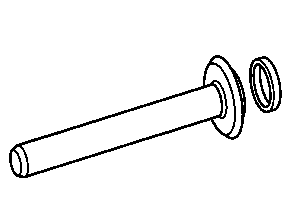

321 589 04 21 00
Adjusting device
395 589 01 63 00
Blocking device
345 589 05 15 00
Drift
001 589 53 21 00
Dial gage


000 589 02 13 00
Torque multiplier
302 589 01 07 00
Claw-type wrench
Referenced documents
- ar3530b0382b Remove/install cover of through-drive with input shaft
- ar3530b045801a Determine installed dimension of drive pinion gear
- ar3530b0459b Disassemble/assemble drive pinion
- ar3530b0464b Remove/install crown wheel with differential