
B35.20-0048-09
Adjustable upper longitudinal tensioner arm |
1 | Adjustable upper longitudinal tensioner arm | 6 | Fixing bracket (upper tensioning arm) | |
2 | Articulation axle | 7 | Chassis stringer | |
3 | Bolt (fixing at the rear axle) | |||
3.1 | Nut | C | Basic measure (adjustable) of the longitudinal tensioner arm | |
4 | Bolt | D | Basic measure to mount the adapters | |
5 | Nut |
B35.20-0049-09
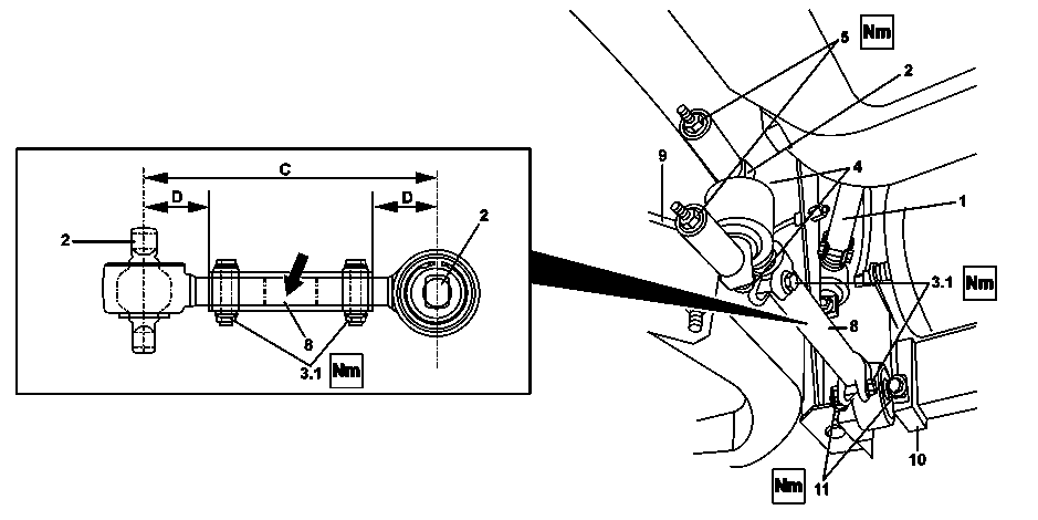
Adjustable lower longitudinal tensioner arm |
1 | Adjustable upper longitudinal tensioner arm | 8 | Adjustable lower longitudinal tensioner arm | |
2 | Pivot shaft | 9 | Fixing bracket (Stringer) | |
3.1 | Nut | 10 | Fixing bracket (lower crossbar) | |
4 | Bolt | 11 | Bolt | |
5 | Nut | C | Basic measure (adjustable) of the tensioner arm | |
7 | Fixing bracket (lower structure) | D | Basic measure to mount the adapters |
| Remove | ||
Danger | Risk of death caused by vehicle slipping or toppling off of the lifting platform. | Align vehicle between vehicle lift columns and position the four support plates at the vehicle lift support points specified by the vehicle manufacturer. | |
Topical note | Notes on self-locking nuts and bolts | ||
1 | If necessary, remove the wheels | ||
2 | Suspend the rear axle so that the longitudinal tensioner arms are not forced | ||
3 | Remove the nuts (5) with the bolts (4) remove the bolt (11) and remove the adjustable lower longitudinal tensioner arm (8) | Do not change the adjustment of the adjustable lower longitudinal tensioner arm (8) when removing it. Any necessary adjustments will be made after mounting when aligning. | |
4 | Remove the nuts (5) the bolts (4) on the fixing bracket (6) and the bolts (3) on the rear axle and remove the adjustable upper longitudinal tensioner arm (1) | Do not change the adjustment of the adjustable upper longitudinal tensioner arm (1). Any necessary adjustments will be made after mounting when aligning. | |
5 | If necessary, dismount the adjustable upper longitudinal tensioner arm (1), or the adjustable lower longitudinal tensioner arm (8), loosen the nuts (3.1) from the locking bolt and remover the rod adapters | ||
| Clean | ||
6 | Clean all the components of the struts | When cleaning, avoid contact of the oscillating cushions with solvents or other detergent products. | |
| Check | ||
7 | Check the longitudinal tensioner arm for damage and wear | When the tensioner arm shows signs of ovalizations in the housings, corrosion and wear | |
| |||
Replace the longitudinal tensioner arm. | |||
8 | Replace the bushes if the longitudinal tensioner arm is not replaced |
| |
| Measure | ||
9 | Mount the adjustable lower longitudinal tensioner arm (8), tighten lightly the nut (3.1) on the bolt in the terminals at the rod and adjust the length | Mount the adjustable lower longitudinal tensioner arm (8) adjusting the basic measure (adjustable) of the tensioner arm (C) and the basic measure to mount the adapters (D) on the adapters when replaced. | |
Clamp flange Bolts | |||
.Basic dimension to mount the adapters on the center rods of the adjustable rear bars, (prior to adjustment) | |||
.Basic dimension (adjustable) of the lower trailing arm right or left rear | |||
10 | Mount the adjustable upper longitudinal tensioner arm (1), tighten lightly the nut (3.1) on the bolts in the rod terminals and adjust the length | Mount the adjustable upper longitudinal tensioner arm (1) adjusting the basic measure (adjustable) of the tensioner arm (C) and the basic measure to mount the adapters (D) on the adapters when replaced. | |
Clamp flange Bolts | |||
.Basic dimension of the upper trailing arms fixed or adjustable rear | |||
.Basic dimension to mount the adapters on the center rods of the adjustable rear bars, (prior to adjustment) | |||
| Install | ||
11 | Install the adjustable upper longitudinal tensioner arm (1) and tighten the bolts (3), the bolts (4) with the nuts (5) with the prescribed torque | Cotnrol arms (longitudinal or transverse) on the rear axles (drive or drag) | |
12 | Install the adjustable lower longitudinal tensioner arm (8) and tighten the bolts (4), the bolts (5) with the nuts (11) with the prescribed torque | Cotnrol arms (longitudinal or transverse) on the rear axles (drive or drag) | |
13 | Install the wheels if they have been removed | ||
14 | Check the alignment of the drive axle using an appropriate device | Before aligning the rear axles, we recommend to check and, if necessary, adjust the front axle steering geometry. | |
15 | If necessary, adjust the aligning of the rear axle, adjust the adjustable lower longitudinal tensioner arm (8) | For adjust the adjustable lower longitudinal tensioner arm (8) loosen the nuts (3.1) on the clamp bolts and turn the bar central rod by the central rectangle. After obtaining the alignment dimension, gently return the key to relieve the pressure on the oscillating cushions. | |
Clamp flange Bolts | |||
16 | Run a test drive and check the vehicle behavior |
Air suspension of the drive rear axle |
Number | Designation | Vehicle 634.011 with rear axle 746.218/225/270/271 with adjustable upper bar | Vehicle 382.185/188/189, 634.011/012/061/071/081 with rear axle 746.218/225/270/271 without Code XF0 | |
BE32.22-B-1001-02A | Basic dimension of the upper trailing arms fixed or adjustable rear | mm | 6751,5 | 6902 |
Air suspension of the drive rear axle |
Number | Designation | Vehicle 382.177/188/189, 634.011/012/061/071/081 with rear axle 746.218/225/270/271 with Code XF0 | Vehicle 634.001/011 with rear axle 746.973/974 with adjustable upper bar | |
BE32.22-B-1001-02A | Basic dimension of the upper trailing arms fixed or adjustable rear | mm | 6472 | 6751,5 |
Air suspension of the drive rear axle |
Number | Designation | Vehicle 382.177/178/185/188/189, 634.011/012/061/071/081 with rear axle 746.973/974 with Code XF0 | Vehicle 382.175/176/178/184/185/186/188/189, 634.011/012/061/071/081 with rear axle 746.973/974 without Code XF0 | |
BE32.22-B-1001-02A | Basic dimension of the upper trailing arms fixed or adjustable rear | mm | 6472 | 6902 |
Air suspension of the drive rear axle |
Number | Designation | Vehicle 634.011 with rear axle 746.218/225/270/271 with adjustable upper bar | Vehicle 382.185/188/189, 634.011/012/061/071/081 with rear axle 746.218/225/270/271 without Code XF0 | |
BE32.22-B-1003-02A | Basic dimension to mount the adapters on the center rods of the adjustable rear bars, (prior to adjustment) | mm | 8515 | 11010 |
Air suspension of the drive rear axle |
Number | Designation | Vehicle 382.177/188/189, 634.011/012/061/071/081 with rear axle 746.218/225/270/271 with Code XF0 | Vehicle 634.001/011 with rear axle 746.973/974 with adjustable upper bar | |
BE32.22-B-1003-02A | Basic dimension to mount the adapters on the center rods of the adjustable rear bars, (prior to adjustment) | mm | 97,510 | 8515 |
Air suspension of the drive rear axle |
Number | Designation | Vehicle 382.177/178/185/188/189, 634.011/012/061/071/081 with rear axle 746.973/974 with Code XF0 | Vehicle 382.175/176/178/184/185/186/188/189, 634.011/012/061/071/081 with rear axle 746.973/974 without Code XF0 | |
BE32.22-B-1003-02A | Basic dimension to mount the adapters on the center rods of the adjustable rear bars, (prior to adjustment) | mm | 97,510 | 11010 |
Air suspension of the drive rear axle |
Number | Designation | Vehicle 634.011 with rear axle 746.218/225/270/271 with adjustable upper bar | Vehicle 382.185/188/189, 634.011/012/061/071/081 with rear axle 746.218/225/270/271 without Code XF0 | |
BE32.22-B-1004-02A | Basic dimension (adjustable) of the lower trailing arm right or left rear | mm | 5961,5 | 5852 |
Air suspension of the drive rear axle |
Number | Designation | Vehicle 382.177/188/189, 634.011/012/061/071/081 with rear axle 746.218/225/270/271 with Code XF0 | Vehicle 634.001/011 with rear axle 746.973/974 with adjustable upper bar | |
BE32.22-B-1004-02A | Basic dimension (adjustable) of the lower trailing arm right or left rear | mm | 5602 | 5961,5 |
Air suspension of the drive rear axle |
Number | Designation | Vehicle 382.177/178/185/188/189, 634.011/012/061/071/081 with rear axle 746.973/974 with Code XF0 | Vehicle 382.175/176/178/184/185/186/188/189, 634.011/012/061/071/081 with rear axle 746.973/974 without Code XF0 | |
BE32.22-B-1004-02A | Basic dimension (adjustable) of the lower trailing arm right or left rear | mm | 5602 | 5852 |
Referenced documents
- ah0000n000101a Notes on self-locking nuts and bolts
- ar3320b145201b Remove/install elastomer bearing on transverse control arm
- ar4010b1101a Remove/install wheels
- as0000z001001a Risk of death caused by vehicle slipping or toppling off of the lifting platform.