AR33.10-T-0010C | Removing and installing left front axle carrier | 11.1.10 |
MODEL 613.364 /365
mit Hinterachse HOSE für O560


T35.10-0014-01
3 Anti-roll bar strut
4 Spring bracket
5 Trailing arm
6 Anti-roll bar bearing bracket
8 Anti-roll bar
9 Upper flange
10 Spacer plates
4 Spring bracket
7 Shock absorber
T32.25-0003-01


T35.15-0002-01
1 Rear axle housing
2 Guide link
11 Bearing cover
2 Guide link
11 Bearing cover
T35.10-0015-01
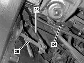

T32.22-0006-01
24 Air suspension valve
25 Linkage
26 Bracket
12 Brake lining wear sensor connector
13 ABS sensor connector
T42.10-0011-01


T35.10-0016-01
4 Spring bracket
14 Diagonal strut
15 Bracket
16 Cross strut
4 Spring bracket
9 Upper flange
17 Diagonal strut
18 Cross strut
T35.10-0017-01
| Removing, installing | ||
Danger! | Risk of injury with trapped or crushed fingers when working on springs or spring-loaded components | Use only approved tensioning devices; additionally shield off hazardous area if necessary. | |
1 | Bleed brake cylinder | e.g. by actuating the parking brake, this operates the brake cylinder by spring load and, at the same time, bleeds it. | |
2 | Raise the vehicle, place on axle stands | - The wheel grippers remain under the wheels after lifting. - The vehicle must be secured on axle stands. | |
3 | Unscrew propeller shaft from drive flange | Removal: - If the propeller shaft is separated at the telescopic section, the positions of the parts with respect to each other must first be marked. - Tie the propeller shaft up to the chassis with a suitable strap, if necessary, secure against the parts sliding apart. | |
Installation: The bolts and nuts must be replaced. | |||
4 | Disconnect brake hoses from brake cylinder | Removal: All lines must be unpressurized. | |
5 | Disconnect cable to ABS sensor at connector (13) | Removal: Nip off Panduit straps holding cable to rear axle. | |
6 | Disconnect cable to brake lining wear sensor at connector (12) | Removal: Nip off Panduit straps holding cable to rear axle. | |
7 | Unscrew vent line from rear axle differential housing | ||
8 | Detach linkage (25) from bracket (26) | Installation: When attaching the linkage (25), the adjustment dimension for the suspension height must be taken into account by maintaining a specified setting height of the air bellows with the vehicle unloaded: | |
Check and adjust vehicle level | |||
9 | Unscrew shock absorber (7) from spring bracket (4) | Installation: The nuts must be replaced. | |
Nut, shock absorber to spring bracket | |||
10 | Remove trailing arm (5) | ||
Bolt, trailing arm to spring bracket | |||
Bolt, trailing arm to underbody | |||
11 | Remove anti-roll bar (8) | Version with code C12 'rear axle anti-roll bar'. | |
12 | Unscrew cross strut (16) behind rear axle from both spring brackets (4) and remove | Nut, cross strut to spring bracket | |
13 | Unscrew diagonal strut (14) behind rear axle from bracket (15) on right spring bracket (4) | Nut, diagonal strut to bracket | |
14 | Unscrew diagonal strut (14) behind rear axle from left spring bracket (4) and remove | Nut, diagonal strut to spring bracket | |
15 | Unscrew diagonal strut (17) in front of rear axle from bracket on left spring bracket (4) | Version without code C12 'rear axle anti-roll bar'. | |
Serrated bolt, diagonal strut to bracket | |||
16 | Unscrew diagonal strut (17) in front of rear axle from cross strut (18) and remove | Version without code C12 'rear axle anti-roll bar'. | |
Serrated bolt, diagonal strut to cross strut | |||
17 | Unscrew guide link (2) from rear axle link bracket | Removal: To do this, the bearing cap (11) must be unscrewed from the link bracket on the rear axle. | |
Installation: The self-locking nuts must be replaced. | |||
Self-locking nut, guide link to rear axle link bracket | |||
18 | Unscrew guide link (2) from bearing bracket on underbody and remove guide link (2) | Removal: To do this, the bearing cap (11) must be unscrewed from the bearing bracket on the underbody. | |
Installation: The serrated bolts must be replaced. | |||
Serrated bolt, guide link to underbody bearing bracket | |||
19 | Lower rear axle and take out from under the vehicle | The air suspension bellows must be released from the upper retainers. | |
20 | Remove rear wheels | To do this, lift rear axle at spring brackets (4) and support on axle stands. | |
21 | Unscrew upper flange (9) from spring bracket (4) | Version without code C12 'rear axle anti-roll bar': Unscrew upper flange (9) and cross strut (18) in front of rear axle from spring bracket (4). | |
Installation: The serrated bolts must be replaced. | |||
Serrated bolt, upper flange to spring bracket | |||
Serrated bolt, upper flange and cross strut to spring bracket | |||
22 | Remove cross strut (18) in front of rear axle | Version without code C12 'rear axle anti-roll bar'. | |
23 | Unscrew upper flange (9) and spring bracket (4) from rear axle | Removal: - Remove upper flange (9) with spacer plates (10), - remove bracket (15), - lift rear axle from spring brackets (4). Version without code C12 'rear axle anti-roll bar': - Remove bracket for diagonal strut in front of rear axle. | |
Installation: The bolted connection is secured with a lock nut. | |||
Nut, upper flange and spring bracket to rear axle housing | |||
24 | Install in the reverse order | Installation: When installing, check wearing parts for re-usability. |
Rear axle shock absorber
Trailing arm, wishbone
Number | Designation | Model 613.364/365 | |
BA35.15-N-1001-02C | Bolt, trailing arm to spring bracket | Nm | 275 |
BA35.15-N-1002-02C | Bolt, trailing arm to underbody | Nm | 275 |
Control arm
Number | Designation | Model 613.364/365 | |
BA35.15-N-1005-03C | Self-locking nut, guide link to rear axle link bracket | Nm | 220 |
BA35.15-N-1006-03C | Serrated bolt, guide link to underbody bearing bracket | Nm | 380 |
Axle housing
Number | Designation | Model 613.364/365 | |
BA35.25-N-1001-01B | Serrated bolt, upper flange to spring bracket | Nm | 370 |
BA35.25-N-1002-01B | Serrated bolt, upper flange and cross strut to spring bracket | Nm | 370 |
BA35.25-N-1003-01B | Nut, upper flange and spring bracket to rear axle housing | Nm | 400 |
BA35.25-N-1004-01B | Serrated bolt, diagonal strut to bracket | Nm | 230 |
BA35.25-N-1005-01B | Serrated bolt, diagonal strut to cross strut | Nm | 230 |
BA35.25-N-1006-01B | Nut, diagonal strut to bracket | Nm | 210 |
BA35.25-N-1007-01B | Nut, diagonal strut to spring bracket | Nm | 210 |
BA35.25-N-1008-01B | Nut, cross strut to spring bracket | Nm | 210 |
Referenced documents
- ar0060t1000b Jacking up and supporting vehicle
- ar3222t7000c Checking and adjusting vehicle level
- ar3235t2210c Remove/install anti-roll bar on rear axle
- ar3510t001004c Removing and installing trailing arm on rear axle
- ar4010t1100b Remove/install wheels
- ar4110t0050b Remove/install propeller shaft
- as0000z000101a Risk of injury caused by pinching or crushing when working on springs or spring bodies that are under tension