35.47-060 Removing, dismantling, assembling and installing crown wheel with differential
Preceding work: Center drive removed (35.47-055). Differential lock removed (35.47-075). |

1 | Ring nut Square mandrel 312 589 04 07 00. |
2 | Outer race |
3 | Tapered roller bearing Heat up to approx. 110°C. |
4 | Tab washers |
5 | Serrated bolts 40 Nm. |
6 | Bearing cover |
7 | Hexagon bolts Initial torque 90 Nm, Final torque 90° angle of rotation. |
8 | Bearing cover Bearing preload 0.10 - 0.25 mm, |
9 | Upper half of differential housing |
10 | Crown wheel Gear backlash 0.20 - 0.28 mm, |
11 | Thrust washer |
12 | Side gear |
13 | Differential spider |
14 | Thrust washers |
15 | Differential bevel gear |
16 | Side gear |
17 | Thrust washer |
18 | Dog clutch (vehicles with differential lock) |
19 | Wire snap-ring (vehicles with differential lock) |
20 | Ring nut Square mandrel 312 589 04 07 00. |
21 | Outer race |
22 | Tapered roller bearing Puller 001 589 40 33 00, |
23 | Lower half of differential housing |
24 | Axle casing |
25 | Adjusting screw Play 0.25 mm = slacken by 1/6 turn. |
26 | Lock nut 100 Nm. |
27 | Sliding block |
28 | Serrated bolts (M 14 x 1) Replace, 280 Nm, wrench socket 352 589 01 09 00. |
29 | Serrated bolts (M 14 x 1.5) Replace, 280 Nm, wrench socket 352 589 01 09 00. |

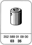
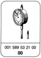


Special tools
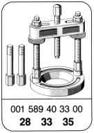
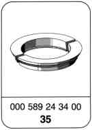

Commercially available tool
Installation adaptation for center drive HL 4/35 e.g. | Schairer GmbH Weidenstraße 5 D-72459 Albstadt Tel.: 07435/336 Fax. 07435/1725 or Richard Bauer GmbH Lorscherstraße 13 D-68642 Bürstadt Tel.: 06206/7448 Fax: 06206/79757 Order no. WBM 0313.02 |
For equipment and tools, also refer to Workshop equipment manual.
Removal
-------------------------------
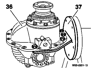
1 Install center drive (36) on installation adaptation (37).

2 Loosen lock nut (26), unscrew adjusting screw (25) and remove sliding block (27) from crown wheel (10).

3 Unscrew serrated bolts (5), remove tab washers (4).
4 Mark bearing covers (6 and 8) and axle casing in relation to each other (arrow).

5 Slacken hexagon bolts (7) and unscrew ring nut (1) using square mandrel (30).
30 Square mandrel 312 589 04 07 00
6 Unscrew hexagon bolts (7) and remove bearing covers (6 and 8).

7 Mark outer races (2 and 21) and tapered roller bearing in relation to each other (arrows) and lift off differential.
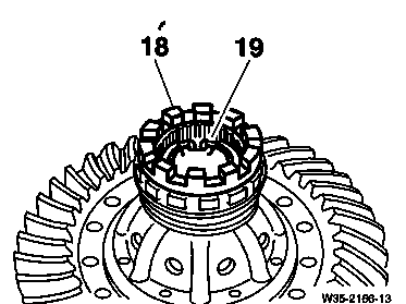
8 Vehicles with differential lock:
8.1 Press wire snap-ring together and remove dog clutch (18).

8.2 Remove wire snap-ring (19).
8.3 Remove ring nut (20) and outer race (21).

Dismantling
-------------------------------
1 Pull off both tapered roller bearings using puller (31), clamp (32) and pressure pad (33).
31 Puller 001 589 40 33 00
32 Clamp 000 589 24 34 00
33 Pressure pad 360 589 02 63 00
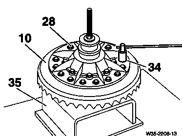
2 Place differential in locator (35) and clamp using suitable thrust pad.
3 Unscrew serrated bolts (28) and using a soft hammer drive down crown wheel (10), press off if required.
35 Locator 337 589 02 31 00
34 Wrench socket 352 589 01 09 00

4 Unscrew serrated bolts (29).
5 Mark both halves of differential housing in relation to each other and unscrew hexagon nut (arrow) on locator.
34 Wrench socket 352 589 01 09 00

6 Remove upper half of differential housing (9), thrust washer (11) and side gear (12) from lower half of differential housing.
7 Remove crown wheel and lower half of differential housing from the locator.

8 Remove differential spider (13) with differential bevel gears (15) and thrust washers (14) from the lower half of the differential housing (23).
9 Remove differential bevel gears (15) and thrust washers (14) from differential spider (13).

10 Remove side gear (16) and thrust washer (17) from the lower half of the differential housing (23).
Assembly
-------------------------------
1 Lubricate thrust washer (17) on both sides and place in the lower half of the differential housing (23) so that the lubrication groove points towards the side gear.
2 Insert side gear (16) into lower half of the differential housing (23).

3 Lubricate differential bevel gears (15) and thrust washers (14) and push onto differential spider.

4 Insert differential spider (13) into lower half of the differential housing (23).
5 Place side gear (12) on the differential spider (13).
6 Lubricate thrust washer (11) and place on the side gear (12) so that the lubrication groove points towards the side gear.

7 Place upper half of the differential housing (9) onto the lower half of the differential housing (23), following the marking (same numbers).

8 Place crown wheel and upper half of differential housing (9) in locator (35) and tighten hexagon nut (arrow) of locator.
9 Tighten serrated bolts (29), 280 Nm.
35 Locator 337 589 02 31 00
34 Wrench socket 352 589 01 09 00

10 Tighten new serrated bolts (28), 280 Nm.
11 Unscrew hexagon nut (arrow) of locator (35) and remove differential housing.
35 Locator 337 589 02 31 00
34 Wrench socket 352 589 01 09 00

12 Heat up both tapered roller bearings (3 and 22) to approx. 110°C and drive home using a suitable drift.

13 Using a feeler gauge, check that the tapered roller bearings (3) abut the differential housing without any play.

Installation
-------------------------------
1 Place differential in axle casing.
2 Place outer races (2 and 21) in axle casing. Follow the marking in the case of used tapered roller bearings (arrows).
3 Position both bearing covers (6 and 8) according to marking and tighten hexagon bolts (7), 30 Nm.
4 Rotate crown wheel several times and apply blows to the bearing covers (6 and 8) using a rubber hammer.
5 Screw in ring nuts (1) until they abut the outer races.
6 Tighten hexagon nuts (7),
Initial torque = 90 Nm.
Final torque 90° angle of rotation.
7 Screw on ring nuts (1) until the tapered roller bearings abut without any play.
30 Square mandrel 312 589 04 07 00

8 Place gauge stand (38) and dial gauge (39) on axle casing.
9 Rotate crown wheel several times.
10 Mount tip of dial gauge under preload on the crown wheel and adjust gear backlash by screwing in the ring nuts.
Specified value: 0.20 to 0.28 mm
30 Square mandrel 312 589 04 07 00
38 Gauge stand 363 589 02 21 00
39 Dial gauge 001 589 53 21 00
11 Measure gear backlash at three points on crown wheel.
12 Check contact pattern.
Note
Drive pinion and crown wheel are manufactured to production tolerances such that an adjustment of the basic dimension and backlash is adequate for correct operation.
Independently of this, the contact pattern of the crown wheel can be checked for monitoring purposes.
To do this, coat two crown wheel teeth at an angle of 180° to each other with Prussian blue. Brake crown wheel in a holding fixture by turning the drive pinion backwards and forwards.

Correct contact pattern:
(under load, crown wheel braked)
Note
Such an ideal contact pattern is unlikely to be achieved in actual practice. It is however important that the contact pattern should at no point be disturbed on the outer edge of the tooth surface.

Incorrect contact patterns:
Contact pattern at foot of tooth flank
Increase installed dimension of drive pinion.
Correcting
Increase the installation distance between the drive pinion and crown wheel slightly (Shim for drive pinion too thin). Install thicker shim
(35.47-065). Check backlash and adjust if required.

Contact pattern at tip of tooth flank
Reduce installed dimension of drive pinion.
Correcting
Reduce the installation distance between the drive pinion and crown wheel slightly. (Shim for drive pinion too thick). Install thinner shim (35.47-065). Check backlash and adjust if required.

Contact pattern at tooth heel
Correcting
Position crown wheel nearer to the drive pinion by turning the ring nuts. Check backlash and adjust if required.

Contact pattern on the tooth chord
Correcting
Position crown wheel further away from drive pinion by turning the ring nuts. Check and adjust gear backlash, if necessary.

13 Rotate crown wheel several times and apply blows to the bearing covers (6 and 8) using a rubber hammer.

14 Mount gauge stand (38) with dial gauge (39) on the back of the crown wheel and mount tip of dial gauge under preload on bearing cover (6).
15 Loosen ring nut (1) and retighten until the dial gauge moves (abuts without any play), then set dial gauge (39) to zero.
16 Screw in ring nut (1) and adjust bearing preload.
Specified value:
New tapered roller bearing 0.20 - 0.05 mm.
Used tapered roller bearing 0.10 - 0.05 mm.
38 Gauge stand 363 589 02 21 00
39 Dial gauge 001 589 53 21 00
Square mandrel 312 589 04 07 00
17 Rotate crown wheel several times and check gear backlash, correct if necessary.

18 Install tab washers (4) with new serrated bolts (5),
40 Nm.

Note
If the passage in the bearing covers is not chamfered (arrows), a 45° chamfer with a width of approx. 3 mm should be ground.
19 Stick sliding block (27) to crown wheel (10) with multipurpose grease, turn crown wheel so that the bore of the sliding block aligns with the bore of the adjusting screw (25).
20 Coat adjusting screw (25) with long-life grease and screw in up to the stop.
21 Unscrew the adjusting screw 1/6 turn and tighten lock nut (26), 100 Nm.
Note
During the setting work, the adjusting screw may be unscrewed no more than 2 turns, otherwise the sliding block can fall into the axle casing.

22 Vehicles with differential lock:
22.1 Engage wire snap-ring (19) in the groove of the splines.
22.2 Compress wire snap-ring (19) and push dog clutch (18) onto the splines.
Note
Ensure wire snap-ring seats correctly in the groove.