05-285 Checking and replacement of valve guides
Preceding work: Cylinder head removed (01-415). | Operation no. of operation texts and work units or standard texts and flat rates 05-3731 |
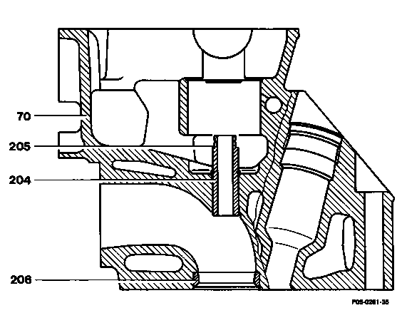
P05-0201-35
Checking Seat for valve stem seal (205) |
check. Replace valve guide (204) if valve stem seal is loose. |
Valve guide (204) | clean. Cylindrical brush 000 589 10 68 00. |
Valve guide (204) inside dia. | check. Plug gauge: 102 589 00 23 00 intake, 117 589 03 23 00 exhaust. Replace valve guide, if reject pin of plug gauge fits completely in the valve guide. |
Replacement Valve guide (204) |
drive out, drive home. Drift: 103 589 03 15 00 intake, 103 589 02 15 00 exhaust. Punch: |
Basic bore of valve guide in cylinder head (70) |
check. If required bore out to next repair size. |
Valve seat insert (206) | check for eccentricity (05-291). |
Valve guides (grey cast iron)
Version and Part No. | Outside dia. (D) | Color marking | Basic bore in cylinder head | Overlap | Valve guide inside dia. (A) | Length (L) | |
|
Intake | Repair size I 601 050 07 24 | 14.240-14.251 | red | 14.200-14.211 | |||
Repair size II 601 050 08 24 | 14.440-14.451 | white | 14.400-14.411 | 0.029-0.051 | 8.000-8.030 | 39.5 | |
|
Exhaust | Repair size I 601 050 10 24 | 14.240-14.251 | red | 14.200-14.211 | |||
Repair size II 601 050 11 24 | 14.440-14.451 | white | 14.400-14.411 | 0.029-0.051 | 9.000-9.050 | 37.7 | |

P05-0187-15


Special tools
000 589 10 68 00
103 589 03 15 00
103 589 02 15 00

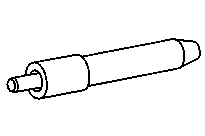

601 589 06 15 00
601 589 05 15 00
102 589 00 23 00


117 589 03 23 00
000 589 21 53 00
000 589 10 53 00


115 589 00 53 00
102 589 00 63 00
102 589 08 63 00


601 589 15 63 00
115 589 01 53 00
Commercially available tools and testers
Designation | e.g. Make | Order no. |
Cylinder head clamping device | Hunger Gräflingerstr. 146 | 221.60.000 |
Broach base bore in cylinder head
(Repair stage)
Decarbonize and clean cylinder head perfectly, particularly the inside of the valve seat inserts. Select correct guide sleeve (2) and remove swarf from the cutters of the broach (1) with a stiff plastic brush or the like.
Note
The broach cutters must be cleaned before each broaching operating.
Provide guide sleeve, basic bore and complete broach with ample supplies of paraffin.

Insert broach into the guide sleeve so that when the guide sleeve rests on the valve seat insert (3) the first cutter of the broach is located in the base bore. In so doing note that the correct side of the guide sleeve is put on the valve seat.
Centre guide sleeve by rotary movements in the valve seat insert.
Note
Drive the broach briskly through with an aluminium mandrel, approx. 130 mm long, and a plastic hammer of approx. 250 g.
P05-0163-17

Note
The high spot (arrow) on the intake valve seat inserts is to be removed before inserting the guide sleeve.
Inserting valve guide
Drive home valve guides with punch and hammer, when the valve guides are not supercooled and the cylinder head is not heated up. Coat valve guides with tallow or oil before driving home.
P05-0164-81
Assignment of guide sleeve - valve seats
Valve seat | Guide sleeve Part No. | Basic bore dia. in cylinder head |
Intake | 102 589 00 63 00 | 14.2 mm |
Exhaust | ||
Intake | 601 589 15 63 00 | 14.4 mm |
Exhaust | ||