03-345 Checking and correcting adjustment of TDC sensor
Preliminary jobs: Radiator removed (20-420). Precombustion chamber on cylinder 1 removed (01-417). | Operation No. of operation texts and operation values or standard texts and flat rates 03-1101 |

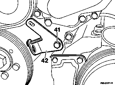

Holder for TDC sensor, engines 601.911/921 and engine 601.912 1st version
Holder for TDC sensor, engine 601.912 2nd version starting 10/85 and engines 602 and 603 from start of production
Cylinder 1 | turn to approx. 10° BTDC, ignition stroke (item 1). |
Gauge (01) | screw into preignition chamber bore and set (item 2). Note |
Engine | turn in running direction until dial gauge pointer stands still (TDC position), set dial gauge scale to zero (item 3). |
Engine | turn until dial gauge moves back 3.22 mm on engines 601.911/912, 602, 603 or until dial gauge moves back 3.65 mm on engines 601.921, 603.97 (item 4). Note |
Holder for TDC sensor (42) or (44) | install locating device 603 589 01 21 00 (item 5). Note |
Holder for TDC sensor (42) or (44) | correct by loosening bolt (41), move holder for TDC sensor until pin on crankshaft pulley or vibration damper catches in locating device |


Special tools
363 589 02 21 00
601 589 07 21 00
603 589 01 21 00
Commercially available tools and testers
Designation | e. g. make | Order no. |
Dial gauge A 1 DIN 878 | Mahr, | 810 |

Note
The holder for the TDC sensor is fastened to the timing case cover.
42 Holder for TDC sensor, engines 601.911/921 and engine 601.912 1st version
44 Holder TDC sensor, engine 601.912 2nd version starting 10/85 and engines 602 and 603 from start of production
Check adjustment of holder and correct, if required:
a) When holder is replaced.
b) When crankshaft and hub, vibration damper and crankshaft pulley are replaced.
c) When timing case cover is removed, installed or replaced.
Testing
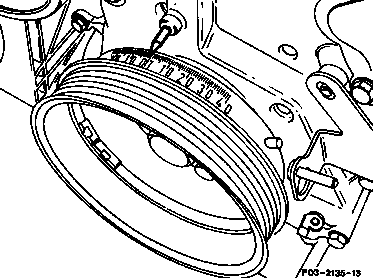
1 Position piston in cylinder 1 to approx. 10° BTDC, ignition stroke.
Holder for TDC sensor, engines 601.911/921 and engine 601.912 1st version

Holder for TDC sensor, engine 601.912 2nd version starting 10/85 and engines 602 and 603 from start of production

2 Screw gauge 601 589 07 21 00 into precombustion chamber bore and attach dial gauge to gauge with 5 mm pretension (small pointer on dial gauge).
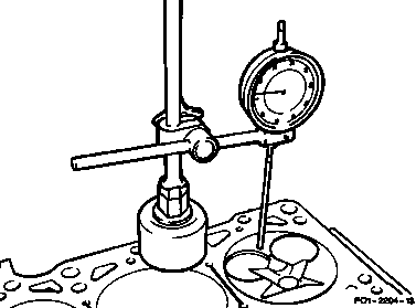
If the cylinder head is removed, the measuring pin on the dial gauge can be positioned directly on the piston crown. Set dial gauge holder
363 589 02 21 00 on crankcase parting surface.
3 Turn crankshaft slowly in normal direction of rotation until large pointer on dial gauge (07) stops (TDC position). Turn dial gauge scale until large pointer points to zero.
01 Gauge
177 Piston crown

4 Turn crankshaft in normal direction of rotation slowly until the gauge moves back
3.22 mm on engines 601.911/912, 602 and 603 or 3.65 mm on engines 601.921 and 603.97.
Note
After the dial gauge has moved back (crankshaft position 20° ATDC) the pin in the crankshaft pulley or in the vibration damper should be located exactly below the TDC sensor (arrow).
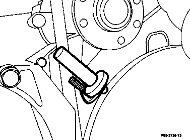
5 Position locating device 603 589 01 21 00 in holder for TDC sensor.
The pin on the crankshaft pulley or on the vibration damper must catch in the groove in the locating device.
If the pin on the crankshaft pulley or on the vibration damper does not catch, correct position of holder for TDC sensor.
Correcting
-------------------------------
6 Loosen holder (42 or 44) with screw (41) and move until pin on crankshaft pulley or on vibration damper catches in the groove in the locating device 603 589 01 21 00.
42 Holder for TDC sensor, engines 601.911/921 and engine 601.912 1st version
7 Screw holder for TDC sensor down tight.
8 Remove dial gauge and gauge
601 589 07 21 00 and locating device
603 589 01 21 00.
44 Holder for TDC sensor, engine 601.912 2nd version starting 10/85 and engines 602, 603 from start of production
Henviste dokumenter
- ar2020p3865ha Af-, påmontering af køler
- ar2020p3865hw
- ra01006010417x
- ra0300601pr02x
- ra0300601ta02x