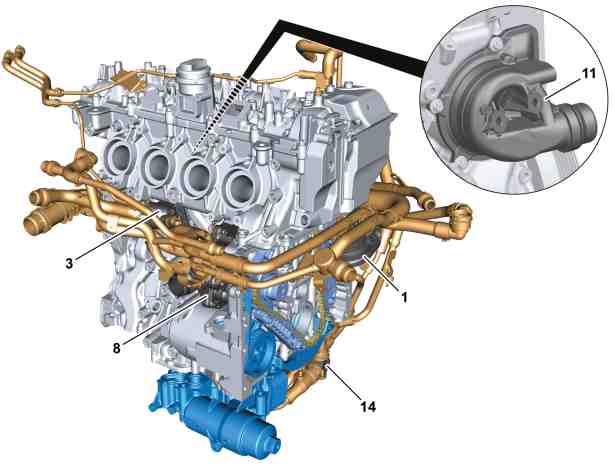
1 | High-temperature circuit coolant pump |
3 | High-temperature circuit coolant thermostat |
8 | Medium-temperature circuit coolant pump |
11 | Medium-temperature circuit coolant thermostat |
14 | Medium-temperature circuit regulation valve |
P20.00-A021-76
P20.00-A040-79
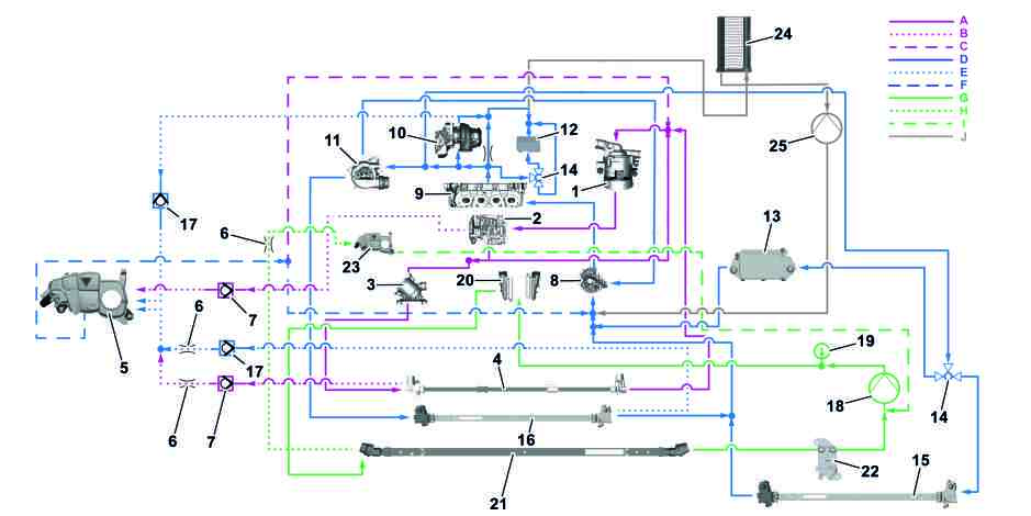
Schematic diagram of coolant circuit |
1 | High-temperature circuit coolant pump | 13 | Transmission oil heat exchanger | 25 | Heating circuit coolant pump | ||
2 | Crankcase | 14 | Medium-temperature circuit regulation valve | A | High-temperature circuit | ||
3 | High-temperature circuit coolant thermostat | 15 | Medium-temperature circuit cooler | B | High-temperature circuit ventilation | ||
4 | High-temperature cooling system | 16 | Medium-temperature circuit additional cooler | C | High-temperature circuit filler line | ||
5 | Expansion reservoir | 17 | Medium-temperature circuit regulation valve | D | Medium-temperature circuit | ||
6 | Restrictor | 18 | Low-temperature circuit coolant pump | E | Medium-temperature circuit ventilation | ||
7 | High-temperature circuit regulation valve | 19 | Low-temperature circuit temperature sensor | F | Medium-temperature circuit filler line | ||
8 | Medium-temperature circuit coolant pump | 20 | Charge air cooler | G | Low-temperature circuit | ||
9 | Cylinder head | 21 | Radiator low-temperature circuit | H | Low-temperature circuit ventilation | ||
10 | Turbocharger | 22 | Evaporator (model dependent) | I | Low-temperature circuit filler line | ||
11 | Medium-temperature circuit coolant thermostat | 23 | Low-temperature circuit expansion reservoir | J | Heating circuit | ||
12 | Engine oil heat exchanger | 24 | Heating circuit heat exchanger |