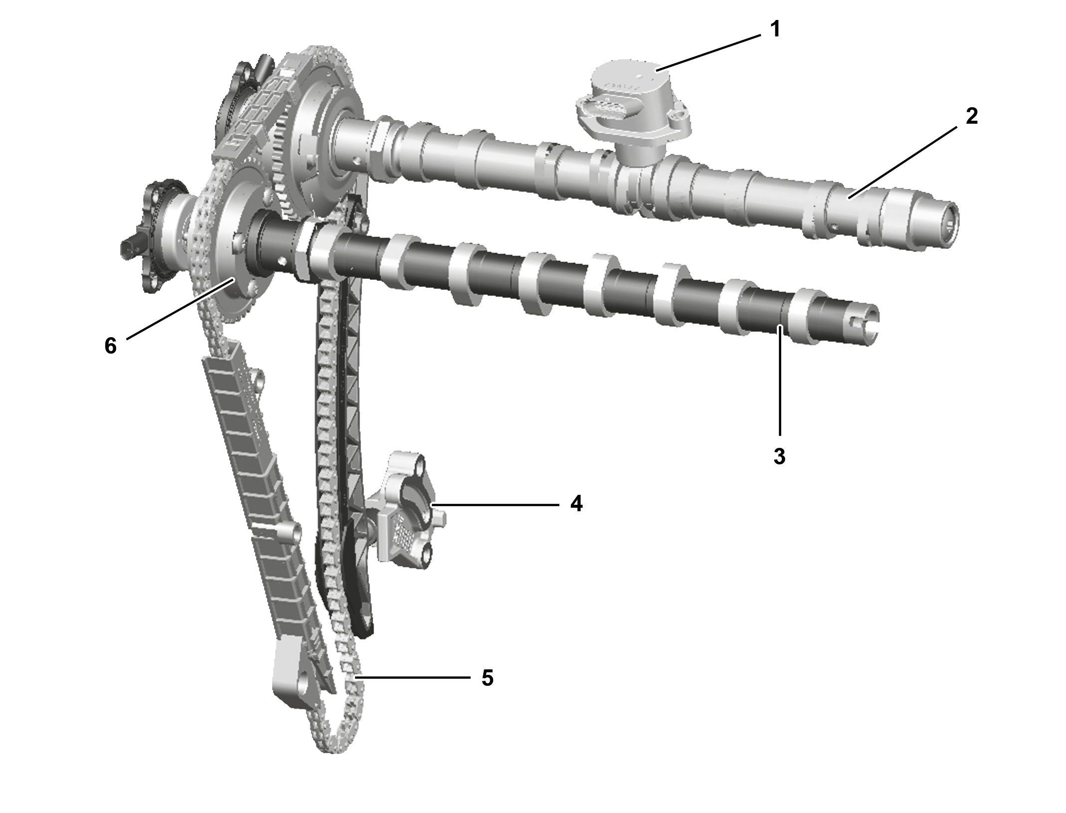
Example illustration of valve train |
1 | Valve lift switching actuator |
2 | Camshaft piece |
3 | Exhaust camshaft |
4 | Chain tensioner |
5 | Timing chain |
6 | Camshaft positioner |
P05.00-A005-76
Overview
This document contains information on:
General
Function requirements
Function
General
The variable valve control comprises the mechanical, hydraulic or electromechanical control of the valve drive.
Variable valve control makes it possible to adapt the valve timing and the valve lift depending on the load and operating condition of the combustion engine.
The variable valve control optimizes the following variables:
Engine output
Fuel consumption
Emissions
Function requirements
Engine management ON (circuit 87M)
Engine in operation
Function
For design reasons, valve timing and valve lift are fixed on combustion engines, i.e. valve lift and crank angle are in a defined ratio to each other. The variable valve train influences the valve timing and the valve lift depending on the load and operating status of the combustion engine.
The variable valve train can be implemented both on the inlet and outlet side by influencing the camshafts.
A distinction is made between the following principles:
Camshaft adjustment
Valve lift adjustment

Valve lift switchover, view of intake camshaft |
1 | Intake camshaft valve lift adjustment actuator |
7 | Tappet |
8 | Curved tracks |
P05.20-A059-76
Valve lift adjustment
In the case of valve lift switchover, the valve lift is changed, i.e. a flat or steep valve lift. With a flat valve lift, i. e. for a small valve lift, throttling losses in partial-load operation and thus fuel consumption can be reduced. To achieve a high torque, a steep valve lift, i.e. a large valve lift, is used in full-load operation. The valve lift adjustment can take place at the intake side and at the exhaust side.
Cylinder deactivation takes place in the case of zero lift. In this connection, the intake and exhaust valves of a cylinder or multiple cylinders remain closed. This results in a dethrottling of the cylinders which increases the efficiency of the remaining cylinders and reduces the fuel consumption.
The valve lift switchover takes place depending on the engine speed, engine load and engine temperature. A smaller valve lift also improves the friction loss which is a thermodynamic advantage. To ensure an optimal combustion in spite of the smaller valve lift, the fuel is injected multiple times. To improve the reduced turbulence of the fuel/air mixture in the combustion chamber around the spark plugs, the fuel/air mixture is ignited multiple times in low partial-load operation. To achieve the full performance characteristics of the major assembly, a switchover takes place to the large valve lift in higher load ranges. Due to the combination of valve lift switchover together with the supercharged spark-ignition engine, fuel-consumption advantages are achieved during engine operation in partial-load operation. With the variable valve lift adjustment, less air can routed into the combustion chamber with a smaller valve lift in partial-load operation, the gas exchange losses and friction losses are thus reduced.
The valve lift switchover is implemented by means of an electromechanical system. The electromechanical system works with actuators that engage mechanically with the camshaft. The camshafts are designed with two parts, i.e a hollow shaft with cam pairs and spiral-shaped grooves that encloses a solid shaft with cams. Depending on the rotational speed and engine load, the actuators engage in the spiral grooves on the rotating camshaft pieces. The actuators move each of these axially to one of the end positions (large or small valve lift). This causes the cams to be moved on the camshaft.

Shown: intake camshaft camshaft positioner |
9 | Catch bolt |
10 | Seal strips with leaf springs |
11 | Compression spring |
12 | Vane-cell piston |
13 | Drive gear |
14 | Cover |
P07.10-A001-75
Camshaft adjustment
During camshaft adjustment, the valve timing is changed by rotation of the camshaft, thereby producing a valve overlap. The camshaft can be rotated in the "advanced" or "retarded" direction while the valve lift remains constant. The camshaft is rotated via camshaft positioners.
In the case of valve overlap, the intake valve opens before the exhaust valve is fully closed. The process occurs at the end of the 4th cycle (gas exhaust) and lasts until the 1st cycle (suction).
If the valve overlap is large, then the intake and exhaust valve open and close advanced. As a result, the combustion temperature drops in the partial-load range and nitrogen oxide emissions (NOx) are reduced. On the exhaust side, repeated intake of exhaust gases causes internal exhaust gas recirculation, leading to a reduction in emissions.
To achieve internal exhaust gas recirculation, the combustion engine control unit sets a large valve overlap at low engine speed and engine load. Less fresh air is admitted because exhaust gases with a low oxygen content are still present in the cylinders. The combustion temperature drops, and the formation of nitrogen oxides (NOx) is reduced. The intake air mass is reduced by the amount of exhaust gases present. The combustion engine control unit shortens the injection duration accordingly.
If the valve overlap is small, then the intake and exhaust valve open and close retarded. In the idle state, small valve overlaps prevent air from overflowing into the exhaust port and exhaust gases from overflowing into the intake port. During full-load operation, a back-flow of air into the cylinders causes a recharging effect. The recharging effect leads to an increase in torque.
The camshaft adjustment is enabled by the combustion engine control unit depending on the engine speed and engine oil temperature. Enable of adjustment of the exhaust camshaft does not occur until a higher engine speed as compared to the intake camshaft. This ensures that the lock position is still reached on the exhaust stroke against the retarded reaction moments of the camshaft even when the oil pressure is low. There is a return spring located for support in each camshaft positioner. If both camshafts are adjusted, adjustment of the exhaust camshaft takes place after a delay (later). This prevents oil supply problems and ensures a reliable functioning of the locking mechanism.
Camshaft adjustment takes place through the use of a camshaft positioner at the power-transmitting ends of the camshaft. The camshaft positioner sets the camshafts with regard to the crank angle, thereby enabling a valve overlap during gas exchange.