AR54.18-P-0020M | Install headliner wiring harness | 15.3.10 |
MODEL 220.0 /1 except code (494a) USA version

P68.30-2790-06
Shown on model 220.0 with code (414a) electric glass tilting/sliding roof and code (220a) Parktronic system and code (882b) interior monitoring (only with anti-theft alarm system)
1 Headliner
2 Main wiring harness
3 Wiring harness for vanity mirror illumination
4 Sun visor pivot bearing
5 Cable set attachment for dome lamp in rear
6 Wiring connector
7 Cable set attachment for rear dome lamp PTS warning indicator
8 Wiring connector
9 Wiring connector
10 Cable set attachment for interior motion sensor transmitter and receiver
E14/6 Left front vanity mirror illumination
E14/7 Right front vanity mirror illumination
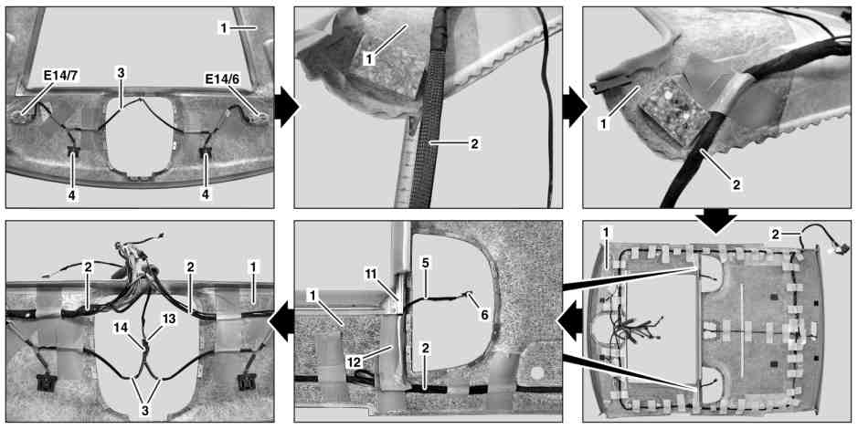
P68.30-2792-09
Shown on model 220.0 with code (414a) electric glass tilting/sliding roof and code (220a) Parktronic system and code (882b) interior monitoring (only with anti-theft alarm system)
1 Headliner
2 Main wiring harness
12 Strips of adhesive tape
13 Connector
14 Coupling
E14/6 Left front vanity mirror illumination
E14/7 Right front vanity mirror illumination
3 Wiring harness for vanity mirror illumination
4 Sun visor pivot bearing
5 Cable set attachment for dome lamp in rear
6 Wiring connector
11 Metal frame for tilting/sliding roof (with code (414a) electric glass tilting/sliding roof)
| Install | ||
| A new main wiring harness (2) must only be installed when replacing the headliner (1). On vehicles with ribbon cable the relevant normal main wiring harness (2) must be used. The headliner model refinement was only carried out from September 2002 to January 2003. Use the old headliner (1) as a guide for routing the main wiring harness (2) | ||
1 | Place new headliner (1) on a clean surface | ||
2 | Support the new headliner (1) with suitable clean spacers, e.g. foamed material or styrofoam blocks. | Do not use any hard or sharp-edged objects, otherwise the covering of the new headliner (1) will be damaged. This prevents the new headliner (1) from bending during the following steps. | |
3 | Clip left front vanity mirror illumination (E14/6) and right front vanity mirror illumination (E14/7) into left and right installation frame . | ||
4 | Connect wiring harness for vanity mirror illumination (3) to left front vanity mirror illumination (E14/6) and right front vanity mirror illumination (E14/7) | ||
5 | Unclip covering from left and right sun visor pivot bearing (4) | ||
6 | Install left and right sun visor pivot bearing (4) in headliner (1) and clip in covering. | ||
7 | Route wiring harness for vanity mirror illumination (3) and fasten to headliner (1) using approx. 10 cm strips of adhesive tape (Tesaband 4657) positioned approx. 10 cm apart as illustrated. | ||
Tesaband 4657 | |||
8 | Measure overhang of main wiring harness (2) at C-pillar of old headliner (1) and ensure new main wiring harness (2) hangs over the same distance. | ||
9 | Route new main wiring harness (2) starting at C-pillar of new headliner (1) and fasten to headliner (1) using approx. 10 cm strips of adhesive tape (Tesaband 4657) positioned approx. 10 cm apart as illustrated. | Do not cross main wiring harness (2) and cable set attachments and press down strips of adhesive tape well otherwise short circuit can occur due to chafing. | |
Tesaband 4657 | |||
10 | Route cable set attachment for interior motion sensor transmitter and receiver (10) and fasten to headliner (1) using approx. 10 cm strips of adhesive tape (Tesaband 4657) positioned approx. 10 cm apart as illustrated. | Begin routing at wiring connector (9), route excessive lengths in loops at main wiring harness (2) and secure using Tesaband 4657 | |
Tesaband 4657 | |||
11.1 | Fasten wiring connector (9) of cable set attachment for interior motion sensor transmitter and receiver (10) to headliner (1) using Tesaband 4657 | On vehicles without code (882b) interior monitoring (only with anti-theft alarm system) | |
Tesaband 4657 | |||
12 | Route cable set attachment for rear dome lamp PTS warning indicator (7) and fasten to headliner (1) using approx. 10 cm strips of adhesive tape (Tesaband 4657) positioned approx. 10 cm apart as illustrated. | Begin routing at wiring connector (8), route excessive lengths in loops at main wiring harness (2) and secure using Tesaband 4657 | |
Tesaband 4657 | |||
13.1 | Fasten wiring connector (8) of cable set attachment for rear dome lamp PTS warning indicator (7) to headliner (1) using Tesaband 4657 | Vehicles without code (220a) Parktronic system (PTS) | |
Tesaband 4657 | |||
14.1 | Route cable set attachment for dome lamp in rear (5) on left and right and fasten to headliner (1) using approx. 10 cm strips of adhesive tape (Tesaband 4657) | Except model 220.0 with code (414a) Electric glass tilting/sliding roof | |
Begin routing at wiring connector (6), route excessive lengths in loops at main wiring harness (2) and secure using Tesaband 4657 | |||
Tesaband 4657 | |||
14.2 | Guide cable set attachment for dome lamp in rear (5) on left and right underneath metal frame for tilting/sliding roof (11) and secure to headliner (1) with strips of adhesive tape (12) (Tesaband 4657) below metal frame for tilting/sliding roof (11) | On model 220.0 with code (414a) Electric glass tilting/sliding roof | |
Press down strips of adhesive tape well otherwise cable set attachment for dome lamp in rear (5) on left and right touches metal frame for tilting/sliding roof (11) after dome lamps have been installed and short circuit can occur due to chafing. | |||
Begin routing at wiring connector (6), route excessive lengths in loops at main wiring harness (2) and secure using Tesaband 4657 | |||
Tesaband 4657 | |||
15 | Connect up connector (13) of main wiring harness (2) and coupling (14) of vanity mirror illumination wiring harness (3) | Connector (13) and coupling (14) have distinct designs and are color coded. | |
16 | Prepare headliner (1) for installation. |
Repair materials
Number | Designation | Order number |
BR00.45-Z-1071-02A | Adhesive tape roll, gray Tesa tape, 50 meters 0.3X50, 236 mm | A 001 989 17 85 |