


906 589 01 21 00
Adjusting device
140 589 16 23 00
Measuring plate
363 589 02 21 00
Dial indicator holder
001 589 82 21 00
Dial gauge

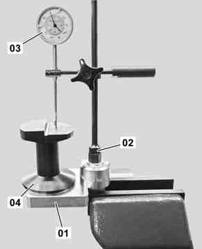
1 | Clamp measuring plate (01) in vise. |
Clamp measuring plate (01) in exact horizontal position. |
2 | Fasten dial indicator (03) to dial indicator holder (02). |
3 | Position dial indicator holder (02) on measuring plate (01). |
Make sure that the dial indicator holder (02) does not make contact with the vise. |
4 | Position gauge block (04) with corresponding measuring surface below the dial indicator (03) on the measuring plate (01). |
The adjustment device contains a gauge block (04) with 2 different measuring surfaces. Depending on the ring gear diameter (Ø 215 mm or Ø 245 mm), use accordingly marked measuring surface for the measuring procedure. |
5 | Set up dial indicator (03) and dial indicator holder (02) so that the dial indicator (03) displays a preload of 30 mm. |
6 | Set dial indicator scale to 0. |
7 | Remove gauge block (04) from measuring plate (01). |
P35.31-2264-12

X | Indentations and material elevations |
P35.31-2266-06
D35.30-A009-02
D35.30-A010-02
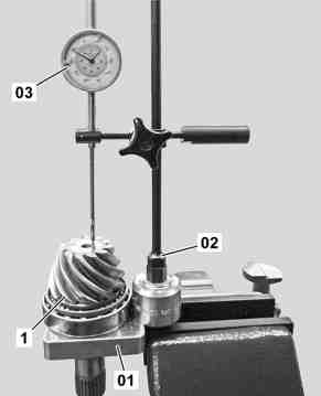
8 | Insert drive pinion (1) into measuring plate (01). |
The drive pinion (1) must be measured with installed tapered roller bearing and its bearing shell. Check that the tapered roller bearing is correctly seated in the bearing shell for the measurement. |
There may be production-related indentations and material elevations (X) at the front of the drive pinion (1). Care must be taken during the measurement to ensure that the dial indicator (03) is positioned at a location that is absolutely flat and free of indentations and material elevations (X). |
To do so, lift measuring tip of dial indicator (03). |
9 | Read off and note preliminary difference dimension on dial indicator (03). |
The preliminary difference dimension is achieved from the difference between the height of the gauge block (04) and the height of the drive pinion (1). |
10 | Calculate actual difference dimension of drive pinion (1) and note down. |
The actual difference dimension of the drive pinion (1) is calculated by subtracting the correction value 14.97 mm from the preliminary difference dimension. |
Example:
21.14 mm (preliminary difference dimension)
-
14.97 mm (correction value)
=
6.17 mm (actual difference dimension of drive pinion (1))