
Press out/in tool
220 589 06 43 00

P33.15-2095-10
Variants of rubber mounts
A Conventional rubber mount
a = 45 mm
B Hydro-mount
b = 60 mm
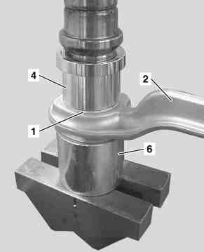
P33.15-2058-02
Press out
1 Apply extraction tool to the unchamfered side of the torque strut and press out the rubber mount (1).
With variant A 220 589 06 43 06 (6) and 220 589 06 43 04 (4) from use press out/in tool.
With variant B 220 589 06 43 06 (6) and 220 589 06 43 05 (4) from use press out/in tool.
2 Check bearing seat in torque strut (2).
Should the bearing seat have clearly noticeable scores, the torque strut (2) should be replaced
Pressing in
3 Turn over the torque strut (2) and align the rubber mount (1) at the chamfered side (chamfer 2 mm x 45°).
During alignment pay attention to the installation position of the rubber mount (1). The elongated hole (3) must point to the center of the ball head (4).

P33.15-2055-07
Variant A
The raised bead (5) can point upwards or downwards.

P33.15-2096-07
Variant B
The lug (6) and the ball head thread (4) must point in the same direction.

P33.15-2056-02
4 Press in rubber mount (1) up to stop.
With variant A 220 589 06 43 06 (6) and 220 589 06 43 07 (7) from use press out/in tool.
With variant B 220 589 06 43 06 (6) and 220 589 06 43 05 (7) from use press out/in tool.

P33.15-2057-02
5 Turn around the torque strut (2), change the press-in tool and press the rubber mount (1) all the way in to the stop once again.
Only on model 211, 219 and 230.
With variant A 220 589 06 43 06 (6) and 220 589 06 43 04 (4) from use press out/in tool.
With variant B 220 589 06 43 06 (6) and 220 589 06 43 09 (4) from use press out/in tool.