MODEL | 212, 218 |
In a removed condition |

212 589 00 43 00
Extraction and installation tool

Mark
1 | Mark rubber mount (1) relative to strut rod (2). |
Shown on model 212 without 4Matic |
A | Marking of rubber mount |
B | Marking of strut rod |
P33.15-2119-11

Press out
All listed special tools are available in the extraction and insertion tool 212 589 00 43 00.
2 | Attach the extraction tool to the non-chamfered side of the strut rod (2) and press out rubber mount (1). |
Use 212 589 00 43 01 (3), 212 589 00 43 03 (4) from the extraction and insertion tool. |
3 | Check bearing seat in torque strut (2). |
Should the bearing seat have clearly noticeable scores, the torque strut (2) should be replaced |
P33.15-2120-11

P33.15-2134-07
Vehicles without 4MATIC |
1 | Rubber mount | A | Marking of rubber mount | C | Bearing core marking | ||
2 | Strut rod | B | Marking of strut rod |
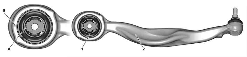
P33.15-2127-07
Vehicles with 4MATIC |
1 | Rubber mount | A | Marking of rubber mount | ||||
2 | Strut rod | B | Marking of strut rod |
Press in
4 |
Attach chamfered side of rubber mount (1) to chamfered side of strut rod (2). |
Align marking of rubber mount (A) with marking of strut rod (B). Vehicles without 4Matic: Align marking for bearing core (C) with ball head. Vehicles with 4Matic: During alignment pay attention to the installation position of the rubber mount (1). |
Generally, the rubber mount (1) is to be positioned in the strut rod (2) such that, in the installation position for the strut rod (2), the marking for the rubber mount (A) faces down and the marking for the bearing core (C) outwards (wheel side). |

5 | Attach insertion tool to the chamfered side of the strut rod (2) and press in rubber mount (1) as far as the end stop. |
Use 212 589 00 43 04 (5), 212 589 00 43 03 (4) from the extraction and insertion tool. |
P33.15-2121-11

6 | Turn over strut rod (2) and press rubber mount (1) again back as far as the end stop. |
Use 212 589 00 43 04 (5), 212 589 00 43 03 (4) from the extraction and insertion tool. |
P33.15-2126-11