Modification notes

Assembly tool
906 589 00 62 00
Front axle carrier
Number | Designation | Front axle 730.4 in model 901, 902, 903, 904 | Model 903.0/4/6, 904.0/4/6 with Code ZG1/ZG2/ZG3 | |||
BA33.10-N-1001-01B | Bolt, front axle carrier to longitudinal frame member | M121.5 | Nm | 125 | 125 | |
Front axle carrier
Number | Designation | Front axle | Front axle | |||
BA33.10-N-1001-01B | Bolt, front axle carrier to longitudinal frame member | M121.5 | Nm | 125 | 125 | |
Front axle steel suspension
Number | Designation | Model 901, 902, 903, 904 with front axle 730.4 | Model 903.0/4/6 and | |||
BA32.20-N-1001-01A | Bolt, lower spring clamp plate to front axle beam | M121.5 | Stage 1 | Nm | 130 | 130 |
Stage 2 | ° | - | - | |||
M8 | Nm | - | - | |||
M10 | Nm | 65 | 65 | |||
Front axle steel suspension
Number | Designation | Model 905 | Model 690.6 with | |||
BA32.20-N-1001-01A | Bolt, lower spring clamp plate to front axle beam | M121.5 | Stage 1 | Nm | 130 | 130 |
Stage 2 | ° | - | - | |||
M8 | Nm | - | - | |||
M10 | Nm | 65 | 65 | |||
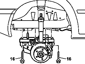
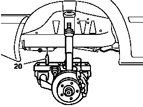
D33.10-0005-01
D33.10-0004-01
1 Bring the front axle into the installation position using the mounted assembly device and telescopic lifter.
2 Lift up front axle and move in guide pin (20) at bores in longitudinal frame member.
Ensure that the shock-absorber struts are inserted in the mounting holes in the body. The incline angle of the crossmember can be changed using the screw plate of the assembly device .
3 Screw in axle mounting bolts (16) on left and right sides .
Figure shows front axle 730.413

D32.35-1102-01
4 Unscrew assembly device (01) .

D32.35-1101-01
5 Screw bolts (arrow) into the front axle and tighten .
Replace nuts.