
P09.41-2320-06
M16/6 Throttle valve actuator
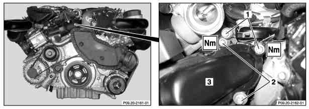
P09.20-2160-04
1 Bolts
2 Bolts
3 Mixing chamber
| Remove/Install | ||
Danger! | Risk of accident caused by vehicle starting off by itself when engine is running. Risk of injury caused by contusions and burns during starting procedure or when working near engine | Secure vehicle to prevent it from moving. | |
Danger! | Risk of death caused by vehicle slipping or toppling off of the lifting platform. | Align vehicle between the columns of the lifting platform and position the four support plates at the lifting platform support points specified by the vehicle manufacturer. | |
| Information on preventing damage to electronic components due to electrostatic discharge | ||
1 | Remove engine trim panel | ||
2 | Remove engine charge air channel upstream of charge air cooler | Installation: To prevent leakages from the engine, check sealing rings and detent springs for damage, clean connecting points thoroughly (but do not grease) and ensure that detent springs are properly seated. See | |
Open and close coupling | |||
3 | Remove right engine intake air duct hose upstream of air filter | ||
4 | Remove muffler downstream of charge air cooler | Installation: Check sealing ring for damage and replace if necessary, in order to avoid leakage. | |
5 | Disconnect the charge air hose at the engine intake air duct downstream of the charge air cooler. | Installation: To prevent leaks from the engine, check sealing rings and detent springs for damage, clean connecting points thoroughly (but do not grease) and ensure that detent springs are properly seated. See | |
Open and close coupling | |||
6 | Undo bolts at the bracket of the throttle valve actuator (M16/6) | Bracket, throttle valve actuator to cylinder head | |
7 | Disconnect electrical connector at the throttle valve actuator (M16/6) | ||
8 | Disconnect electrical connectors from glow output stage. | ||
9 | Disconnect the connector at the charge pressure sensor (B5/1) | ||
10 | Undo bolt at the bracket of the glow output stage at the cylinder head | ||
11 | Unscrew bolts (1) of mixing chamber (3) at the charge air distribution pipe | Mixing chamber to charge air distribution pipe | |
12 | Unscrew bolts (2) of mixing chamber (3) at the charge air distribution pipe | Mixing chamber to charge air distribution pipe | |
13 | Push the hose and tubing bracket at the flange of the mixing chamber (3) upwards | ||
14 | Lift mixing chamber (3) up and out | Installation: Replace sealing rings to avoid leaks and damage at the engine. | |
15 | Install in the reverse order |
Intake manifold
Number | Designation | Engine | ||
BA09.20-P-1001-01Q | Bolt, mixing chamber to charge air distribution pipe | M6 | Nm | 9 |
Charge air pipe/charge air cooling
Henviste dokumenter
- ah5400p000101a Oplysninger med henblik på at undgå skader på elektroniske komponenter på grund af elektrostatisk afladning
- ar0110p2405pi
- ar0940p6925pi
- ar0941p131101al
- ar0941p8623pi
- ar0941p8625pi
- as0000z000501a Fare for ulykke ved automatisk igangsætning når motoren kører. Fare for personskade på grund af knusning og forbrænding, hvis der arbejdes mens motoren startes eller kører
- as0000z001001a Livsfare, hvis køretøjet glider ned fra eller tipper på liften.