
D07.04-1246-09
1 | Electrical connector | 4 | Electrical line | 7 | Electrical line | ||
2 | Circulation pump | 5 | Clamp | 8 | Clamp | ||
3 | Bracket | 6 | Heat shield | 9 | Screw |
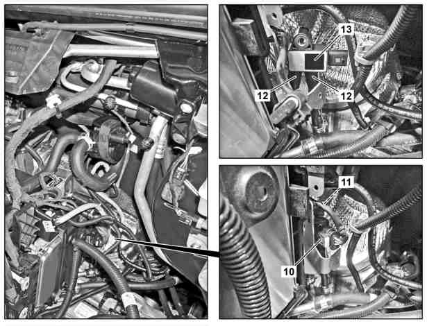
10 | Electrical connector |
11 | Screw |
12 | Hoses |
13 | Differential pressure sensor |
D07.04-1247-06
Caution | Risk of injury caused by scraping or cutting body parts on sharp vehicle parts | Always wear protective gloves when working on or near sharp and non-deburred vehicle parts. | |
Warning | Risk of burn injuries, suffocation and poisoning when working on the exhaust system and the components connected to it. Risk of suffocation and risk of poisoning caused by inhalation of gaseous and solid components of the exhaust. Risk of poisoning caused by skin contact with solid components of the exhaust. | Wear protective clothing and safety glasses. Use the extraction system. Move people out of the hazard area. | |
Warning | Risk of injury. Skin or eye injuries may result when handling hot or glowing objects. | Wear protective gloves, protective clothing and safety glasses, if necessary. | |
| Remove/install | ||
1 | Remove air filter housing | ||
2 | Disconnect electrical connection (1) | ||
3 | Remove circulation pump (2) from bracket (3) and move out of the working area | ||
4 | Remove electric lines (4) with clip (5) from heat shield (6) | Installation: Check clip (5) for damage. | |
Depending on findings | |||
| |||
Replace damaged clip (5). | |||
5 | Remove electric line (7) with clip (8) from heat shield (6) | Installation: Check clip (8) for damage. | |
Depending on findings | |||
| |||
Replace damaged clip (8). | |||
6 | Remove bolt (9) | M6 | |
7 | Remove heat shield (6) upward | Installation: Ensure that heat shield (6) is seated correctly. | |
8 | Disconnect electrical connection (10) | ||
9 | Remove screw (11) | Bolt, differential pressure sensor to bracket | |
10 | Remove hoses (12) from differential pressure sensor (13) | Removal: Mark assignment of the hoses (12) relative to the differential pressure sensor (13). | |
Installation: Observe assignment of hoses (12). | |||
11 | Remove differential pressure sensor (13) | ||
12 | Install in the reverse order | ||
| Check | ||
Warning | Risk of accident from vehicle starting off by itself when engine running. Risk of injury (bruises and burns) resulting from working on the engine while it is being started or when it is running. | Secure vehicle to prevent it from starting off by itself. Wear closed and snug-fitting work clothes. Do not touch hot or rotating parts. | |
13 | Check for leak tightness with engine running | Visual inspection only. |
Henviste dokumenter
- ar0910d1150tsf
- as0000z000201a Fare for personskade på hud og øjne ved håndtering af varme eller glødende genstande
- as0000z000501a Fare for ulykke ved automatisk igangsætning når motoren kører. Fare for personskade på grund af knusning og forbrænding, hvis der arbejdes mens motoren startes eller kører
- as0000z001701a Fare for personskade på grund af snitsår eller hudafskrabninger grundet skarpkantede køretøjsdele
- as4900z000101a Forbrændings-, kvælnings- og forgiftningsfare ved arbejde på udstødningssystemet og dermed forbundne komponenter. Kvælningsfare og fare for forgiftning ved indånding af gasformede og faste komponenter i forbrændingsgassen. Fare for