
1 | Segment disc |
1a | Edge |
2 | Segment disc |
2a | Bearing slot |
3 | Cylinder head cover |
P05.10-2470-06
| Remove/install | ||
1 | Remove both Hall sensors of the camshafts. | ||
2 | Remove engine air intake duct upstream of air filter. | ||
3 | Turn engine at the center bolt of the crankshaft in the direction of engine rotation to top dead center (TDC) of cylinder 1. | The TDC marking on belt pulley/ vibration damper must be aligned with positioning edge on timing case cover. | |
Socket wrench bit | |||
| Check | ||
4 | Check basic position of camshafts. | Check the basic position of the camshafts by means of a visual check of the Hall sensor openings on the cylinder head cover (3). | |
To check the exhaust camshaft adjustment, the edge (1a) of the partial segment of the segment disk (1) must be visible in the center of the Hall sensor opening. To check the intake camshaft adjustment the bearing slot (2a) of the segment disc (2) must stand in the middle in the Hall sensor opening (picture). | |||
If the check was not successful, | |||
| |||
Set basic position of camshafts. | |||
5 | Install in the reverse order. |
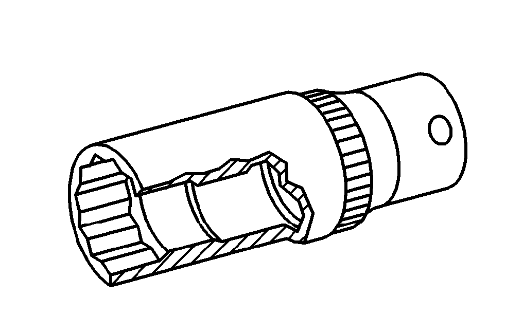
001 589 65 09 00
Socket wrench bit
Henviste dokumenter
- ar0520p6020mrd
- ar1510p1999mrd Af-, påmontering af Hall-sensor til knastaksel