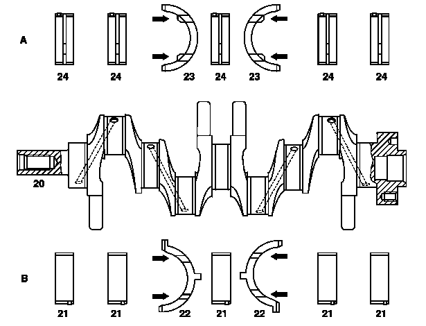
601DShown on engine 601: Oil grooves (arrow) in thrust plates (22) and (23) must point towards thrust collars of crankshaft. |
A | Cylinder crankcase |
B | Bearing cap |
20 | Crankshaft |
21 | Main bearing in bearing cap |
22 | Thrust plates (axial bearings) in bearing caps |
23 | Thrust plates (axial bearing) in cylinder crankcase engine 601 3rd main bearing = thrust bearing engine 602 4th main bearing = thrust bearing engine 603.5 main bearing = thrust bearing |
24 | Main bearing in crankcase |
P03.20-0216-06
| Remove | ||
1 | Remove crankshaft | Take into account the fit and bearing diagram | |
Bearing diagram for crankshaft | |||
Installation: Check length of crankshaft bearing cap bolt, replace if necessary (version 2) | |||
Bolt for crankshaft bearing cap | |||
Bolt for crankshaft bearing | |||
2 | Clean engine parts | If bearing damage has occurred, possibly present chips must be removed from connecting rod bores as well as crankshaft and cylinder crankcase oil ducts | |
| |||
Clean, seal main oil duct | |||
| Check | ||
3 | Check connecting rod, repair if necessary | ||
| |||
4 | Check, repair crankshaft | | |
5 | Mount crankshaft radially in bearings | ||
Main bearing play | |||
Connecting rod bearing play | |||
Engine 601, 602.91/96, 603.91/96/97Crankshaft bearing | |||
Main bearing shells standard dimension for crankcase and bearing cap Ø 58.00 mm | |||
Engine 601, 602 (except 602.98), 603Crankshaft journal-Ø | |||
Engine 601, 602 (except 602.98), 603Connecting rod journal-Ø | |||
Bolt for crankshaft bearing cap | |||
Engine 601, 602 (except 602.98), 603Connecting rod screw (stretch shank) | |||
Engine 601, 602 (except 602.98), 603Connecting rod bolt (stretch bolt) | |||
Dial gage | |||
A radial mounting for the main bearings is possible for standard dimension crankshafts by assigning the color-coded bearing shells, see | |||
| |||
Assign crankshaft bearing shells | |||
6 | Mount crankshaft axially | ||
Main bearing play | |||
Engine 601, 602 (except 602.98), 603Fit bearing journal width | |||
Engine 601, 602 (except 602.98), 603Bolt for crankshaft bearing cap | |||
Dial gage | |||
Dial indicator holder | |||
7 | Install in the reverse order |
Check values for cylinder crankcase |
Number | Designation | Engine 601, 602.91/96, 603.91/96 | Engine 603.97 | ||
BE01.40-P-1001-02D | Crankshaft bearing | Basic bore diameter | mm | 62,500...62,519 | 62,500...62,519 |
Basic bore width at fitted bearing | mm | 19,979...20,000 | 19,979...20,000 | ||
Permissible out-of-roundness and taper of basic bore | mm | 0,02 | 0,02 |
Check values of crankshaft |
Number | Designation | ENGINE 601 up to 06/84 | ENGINE 601 as of 07/84, 602 except 602.98, 603 | ||
BE03.20-P-1001-02C | Crankshaft journal-Ø | Standard size | mm | 57,940...57,965 | 57,940...57,965 |
Repair stage 1 | mm | 57,700...57,715 | 57,700...57,715 | ||
Repair stage 2 | mm | 57,450...57,465 | 57,450...57,465 | ||
Repair stage 3 | mm | 57,200...57,215 | 57,200...57,215 | ||
Repair stage 4 | mm | 56,950...56,965 | 56,950...56,965 |
Check values of crankshaft |
Number | Designation | ENGINE 601 up to 06/84 | ENGINE 601 as of 07/84, 602 except 602.98, 603 | ||
BE03.20-P-1002-02C | Connecting rod journal-Ø | Standard size | mm | 47,940...47,965 | 47,940...47,965 |
Repair stage 1 | mm | 47,700...47,715 | 47,700...47,715 | ||
Repair stage 2 | mm | 47,450...47,465 | 47,450...47,465 | ||
Repair stage 3 | mm | 47,200...47,215 | 47,200...47,215 | ||
Repair stage 4 | mm | 46,950...46,964 | 46,950...46,964 |
Check values of crankshaft |
Number | Designation | ENGINE 601 up to 06/84 | ENGINE 601 as of 07/84, 602 except 602.98, 603 | ||
BE03.20-P-1003-02C | Fit bearing journal width | Standard size | mm | 26,500...26,520 | 24,500...24,533 |
– | mm | 26,600...26,620 | 24,600...24,633 | ||
Repair stage | mm | 26,700...26,720 | 24,700...24,733 | ||
– | mm | 26,900...26,920 | 24,900...24,933 | ||
– | mm | 27,000...27,020 | 25,000...25,033 |
Connecting rod |
Number | Designation | ENGINE 601, ENGINE 602.000/912/962, ENGINE 602.93/94, ENGINE 603.91/931/96/971/972 up to 30.11.90, ENGINE 603.970 up to 31.08.90 | ENGINE 601, ENGINE 602.000/912/962, ENGINE 602.93/94, ENGINE 603.91/96/971 as of 01.12.90 up to 31.10.92, ENGINE 603.970 as of 01.09.90 up to 31.10.92 | |||
BA03.10-P-1001-01C | Connecting rod screw (stretch shank) | Stage 1 | New | Nm | – | 45 |
Used | Nm | – | 40 | |||
Stage 2 | ° | – | 90 | |||
Picture | - | |||||
Connecting rod |
Number | Designation | ENGINE 601, ENGINE 602.000/912/962, ENGINE 602.93/94, ENGINE 603.91/931/96/971/972 up to 30.11.90, ENGINE 603.970 up to 31.08.90 | ENGINE 601, ENGINE 602.000/912/962, ENGINE 602.93/94, ENGINE 603.91/96/971 as of 01.12.90 up to 31.10.92, ENGINE 603.970 as of 01.09.90 up to 31.10.92 | ||
BA03.10-P-1002-01C | Connecting rod bolt (stretch bolt) | Stage 1 | Nm | 30 | – |
Stage 2 | ° | 90 | – | ||
Picture | - | ||||


001 589 32 21 00
Dial gage
363 589 02 21 00
Dial indicator holder
Henviste dokumenter
- ah0320n435101b Lejeskema krumtapaksel
- ar0310p6111aw
- ar0320p435501aw
- ar0320p435502aw
- ar0320p436001ha