AN43.40-D-0001-02TS | Install retarder | ||
Danger | Risk of death caused by vehicle slipping or toppling off of the lifting platform. | Align vehicle between vehicle lift columns and position the four support plates at the vehicle lift support points specified by the vehicle manufacturer. | |
Danger | Risk of explosion caused by paint vapors igniting. Risk of poisoning caused by inhaling paint vapors. | No smoking! No open fire! Use respiratory protection, protective clothing, gloves, safety glasses and protective skin cream. Ensure that the area is well ventilated. | |
Warning | Risk of injury. Moving parts can pinch, crush or, in extreme cases even sever extremities. | No parts of the body or limbs should be within the operating area of mechanical components when moving components. | |
Caution | Risk of injury caused by scraping or cutting body parts on sharp vehicle parts | Always wear protective gloves when working on or near sharp and non-deburred vehicle parts. | |
Topical note | Notes on self-locking nuts and bolts | ||
Topical note | Information on preventing damage to electronic components due to electrostatic discharge | ||
Topical note | General notes on touch-up applicators and paint spray cans | ||
| 000 588 11 62 00 Major assembly mount | ||
| 000 588 10 62 00 Support plate |
Model | 907.1 |
with code BR9 (Provision for fitting Telma retarder) | |
with code IR6 (Wheelbase 4325 mm, overhang 1615 mm) | |
with code IT5 (5.0 tonner) | |
Model | 907.2 |
with code BR9 (Provision for fitting Telma retarder) | |
with code IR6 (Wheelbase 4325 mm, overhang 1615 mm) | |
with code IT5 (5.0 tonner) | |
Model | 907.6 |
with code BR9 (Provision for fitting Telma retarder) | |
with code IR6 (Wheelbase 4325 mm, overhang 1615 mm) | |
with code IT5 (5.0 tonner) | |
Model | 907.6 |
with code BR9 (Provision for fitting Telma retarder) | |
with code IR7 (Wheelbase 4325 mm, overhang 2015 mm) | |
with code IT5 (5.0 tonner) |

1 | Remove electrical connector (1) and electric lines (2, 3) from factory-fitted subharness (4). |
To do so, cut through the cable ties. |
D43.40-A034-06

D43.40-A015-09
a | Dimension (approx. 100 mm) | c | Dimension (approx. 145 mm) | |
b | Dimension (approx. 155 mm) |
Prepare crossmembers (5, 6)
2 | Remove underbody protection in hatched areas on crossmembers (5, 6). |
Observe dimensions (a, b, c). |
Surfaces previously covered by the underbody protection must be flat. |
If paint on crossmembers (5, 6) was damaged: |
|
Mend damage using a suitable brush or touch-up paint pen. |
Use only paints or touch-up paint pens approved by Daimler AG: |
3 | Clean contact surfaces in hatched areas on crossmembers (5, 6) . |
4 | Remove underbody protection in threads in hatched areas. |

Prepare retarder (7)
5 | Secure retarder (7) on major assembly mount using mounting plate. |
Aid of helper required. |
Commercially available devices/tools |
6 | Remove nuts (8) with washers. |
To do this, counterhold the screws. |
7 | Remove mounting support (9). |
D43.40-A016-11

8 | Position mounting support (9) on crossmembers (5, 6). |
Ensure that there is no underbody protection between mounting support (9) and crossmembers (5, 6). |
9 | Tighten screws (10, 11) lightly by hand. |
10 | Tighten bolts (10). |
11 | Tighten screws (11). |
D43.40-A017-04
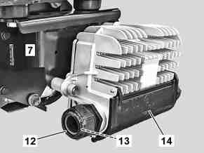
12 | Remove union nut (12) and seal (13). |
13 | Open cover (14). |
D43.40-A020-01

14 | Remove nuts (15.1, 15.2). |
D43.40-A035-01

15 | Connect electrical subharness (16) to electrical connector (1). |
16 | Guide electrical subharness (16) and electric lines (2, 3) through hose (17). |
17 | Slide union nut (12) and seal (13) onto hose (17). |
18 | Remove covers (18). |
D43.40-A036-06

D43.40-A022-09
d | Dimension (45 mm) | e | Dimension (< 10 mm) |
19 | Position seal (13). |
Observe dimension (d). |
20 | Guide hose (17) as well as electric lines (2, 3) and plug of electrical subharness (16) into retarder control unit (19). |
21 | Attach union nut (12). |
Tighten union nut (12) until dimension (e) is reached. |
22 | Connect electric lines (2, 3). |
Electric line (2): "RD" |
23 | Attach nuts (15.1, 15.2). |
24 | Connect plug of electrical subharness (16) to retarder control unit (19). |
25 | Close cover (14). |

D43.40-A021-08
26 | Install retarder (7). |
To do so, position retarder (7) on crossmembers (5, 6) and mounting support (9). |
27 | Tighten screws (20, 21) and nuts (8) with washers lightly by hand. |
To do so, counterhold screws of nuts (8). |
28 | Tighten screws (20). |
29 | Tighten screws (21). |
30 | Tighten nuts (8). |
To do this, counterhold the screws. |

31 | Attach holder (22) to hose (17). |
32 | Tighten holder (22) on retarder (7) with screw (23) lightly by hand. |
To do so, counterhold nut. |
33 | Secure hose (17) with electric lines (2, 3) and electrical subharness (16) to factory-installed electrical wiring harness in sections using cable ties. |
Do not kink hose (17) with electric lines (2, 3) and electrical subharness (16) and ensure chafe-free routing. |
34 | Tighten screw (23). |
To do so, counterhold nut. |
D43.40-A023-11
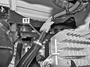
35 | Seal hose (17) as shown . |
D43.40-A024-01
Henviste dokumenter
- ah0000n000101a Oplysninger om selvlåsende bolte og møtrikker
- ah5400p000101a Oplysninger med henblik på at undgå skader på elektroniske komponenter på grund af elektrostatisk afladning
- ah9800p940906a Generelle oplysninger om lakstifter og lakspraydåser
- as0000z000901a Fare for personskade som følge af klemning af legemsdele, i værste fald fare forafskæring af legemsdele ved indgreb i mekanikken
- as0000z001001a Livsfare, hvis køretøjet glider ned fra eller tipper på liften.
- as0000z001701a Fare for personskade på grund af snitsår eller hudafskrabninger grundet skarpkantede køretøjsdele
- as9800z000201a Fare for eksplosion på grund af antændelse af lakdampe. Fare for forgiftning på grund af indånding af lakdampe
- ws0100p0092b
- ws2600p3309b