Verwendung in FG 06/47/Satz B/C |
|
000 588 12 82 00
Minimum requirements:
The connection set, including the entire equipment and the related documentation fulfills the legal regulations, directives, specifications, and guidelines that are valid in the respective country at the time of the order.
The connection set is designed for operation with gaseous hydrogen (purity 5.0 or better quality).
The connection set is designed for filling the vehicle tank system of Mercedes-Benz F-CELL vehicles.
Rinsing the connection set with hydrogen is ensured after changing the cylinder bundle.
Connection to a hydrogen cylinder bundle – purity 5.0 (or better) – 300 bar filling pressure (thread W 21.80 x 1/14" left), is possible.
Operation with a primary pressure P1 of 300 bar is ensured.
The secondary pressure P2 can be adjusted continuously via a pressure regulating device from 0 bar to 200 bar.
One manometer is installed in each case for pressure monitoring of the primary and secondary pressure.
Adaptation of the flow volume in the connection set is carried out using a cover with a hole diameter of 1.6 mm.
A prefilter with 50 μm or finer is installed.
The model plate corresponds to the valid legal regulations, directives, specifications, and guidelines of the respective country. The following information is listed as a minimum:
Manufacturer
Manufacturer's designation
CE approval
Maximum primary pressure P1 in bar
Adjustable secondary pressure P2 in bar
Medium: Hydrogen, purity 5.0 or better
The refueling hose (high-pressure hose at least 300 bar) has a length of 5000 mm 500 mm.
The refueling hose has a filling and bleed line. Note: The bleed line is necessary for pressure relief between the fill coupling on the vehicle and the nozzle.
The nozzle corresponds to the SAE J2600 standard and can be connected to and disconnected from a vehicle tank connection for 700 bar.
A holding device for the nozzle is attached to the connection set. - A breakaway device is integrated.
A breakaway device is integrated.
Note:
By applying a tractive force to the refueling hose, the refueling hose is decoupled when releasing the breakaway device and the feed line is closed automatically.
The breakaway device can be attached again and but back into operation without factory repair after releasing.
All components, connections and valve positions are clearly marked.
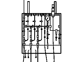
A flow chart with designation of all components, connections, and valve positions is attached to the connection set.
All components of the connection set are installed on a carrier (metallic plate, housing, cabinet, etc.).
The connection set is protected from weather effects.
The connection set is designed for assembly on a wall or as a fixed installation with stands.
A maintenance and inspection log book in the country-specific language is contained in the package contents.
An operator's manual and safety instruction in the country-specific language is contained in the package contents.

P06.10-A024-09
1 | Cylinder bundle | 9 | Outlet shutoff valve | |
2 | Bundle replacement purge valve | 10 | Safety valve | |
3 | Drain line with muffler | 11 | Nozzle | |
4 | Inlet shutoff valve | 12 | Supply pipe | |
5 | Check valve | 13 | Filling line | |
6 | Pressure regulator | 14 | Bleed line coupling point | |
7 | Filter | 15 | Breakaway device | |
8 | Filling device purge valve |