Starter
Number | Designation | Engines | |
BA15.30-N-1002-01B | Nut, terminal 30 at starter | Nm | 30 |
BA15.30-N-1003-01B | Nut, terminal 31 at starter | Nm | 25 |
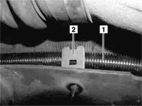
W15.18-1024-01
1 Bend bracket (2) in longitudinal frame member upward a little and remove engine wiring harness (1) between longitudinal frame member and engine.
Installation: Before installing the repair cable set, place a tie strap in the bracket (2).
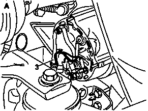

W15.18-1011-01
2 Remove wiring harness (3) from generator
Installation: Only fit the upper tie strap to the bracket of the alternator.
A Shown with three-phase current generator
B Shown with compact generator
W15.18-1030-01

W15.18-1026-01
3 Remove wiring harness (4) to starter.
Installation: The battery line (4.1) must be rotated by 180° before installing the new cable set.
If the lead to circuit 50 is present in the MR/PLD wiring harness it must be reused. In this case the black/yellow (sw/ge) lead in the repair wiring harness must be cut off and the cable end sealed with suitable insulating tape.

4 Remove engine wiring harness (5) to injection valve and engine wiring harness (6) to flame starting system.
Installation: On vehicles without flame starting system cut leads off of new wiring harness and seal cable ends with suitable insulating tape.
W15.18-1025-03
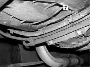
W15.18-1022-01
5 Remove engine wiring harness (7) below oil pan.
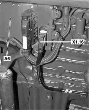
W15.18-1023-02
6 Disconnect connector (X1.16) from MR/PLD control unit (A6).
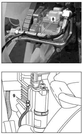
7 Remove connector to AC compressor (8) and high/low pressure switch (9).
Installation: On vehicles without an air conditioning system, cut lines off of new cable set and seal line ends with suitable friction tape.
W15.18-1021-03
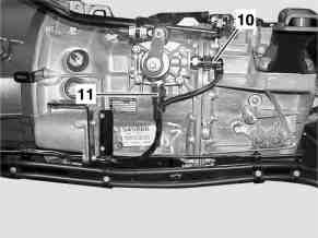
W15.18-1019-01
Shown on transmission G60
8 Remove engine wiring harness to transmission.
9 Remove reverse gear switch connector (10) from transmission.
10 Remove neutral position connector (11) from transmission.
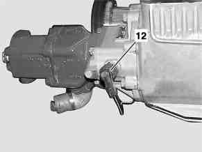
W15.18-1020-01
11 Remove PTO connector from transmission.
Installation: On vehicles without power take-off, tie line to engine cable set.