83-1101 Testing CO2 emission value
A. With CO2 measuring unit
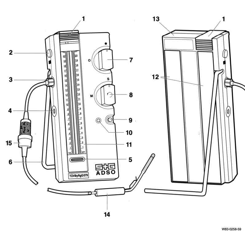
1 Transportation securing device | |
2 Unlocking device | |
3 Gas input | |
4 Gas output | |
5 Adjusting wheel | |
6 Mounting bracket | |
7 Rotary knob (zero point) | |
8 Rotary knob (suction/measurement) | |
9 Pump button | |
10 Battery check | |
11 CO2 scale | |
12 Magnetic tapes | |
13 Housing cover | |
14 Emission sensor | |
15 Dessicator |
Commercially available tool Company
ADSO CO2 measuring unit | S+G Schmitt Meßgerätebau GmbH Rheinhorststraße 14 D-6700 Ludwigshafen Telephone 0621/67 4087 | |
Measuring CO2 emission value
Note
- If the emission values cannot be adjusted, the distance between the impeller and the blower housing is excessive. Adjust combustion blower (83-5557).
- Before the measurement check the dessicator, replace dessicant if blue pellets are light blue or beige.
- The CO2 value must be measured:
- after repairs to the burner.
- in the event of combustion irregularities.
1 Set vehicle heating and vehicle blower to maximum.
2 Switch on heater unit.
After approximately 5 minutes, measure the CO2 value.
In the meantime, prepare the measuring unit.

3 Fold open mounting bracket (6) of measuring unit and place unit on a horizontal base.
4 Pull up the transportation locking device (1).
5 Position rotary knob (7) on "0". The red fluid is now set to the zero line.

Note
Small deviations from the zero line can be readjusted by turning the adjusting wheel (5).
- Turning anticlockwise = fluid rises.
- Turning clockwise = fluid falls.

If the fluid does not let itself be positioned on the zero line:
- Turn rotary knob (8) outwards to the right.
- Suck on the suction hose several times using the mouth.
This eliminates any air bubbles in the measuring system caused by transportation.

6 Turn rotary knob (7) to the dot .
Measuring
Messen
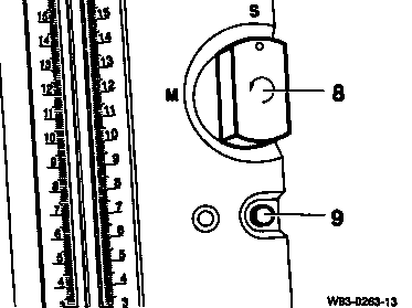
7 Turn rotary knob (8) to position "S"
(= suction) and plug sensor into the exhaust pipe.
Note
The measuring unit can be held by hand or secured to the vehicle using the magnetic strip.
8 Keep the red button (9) pressed for approx. 15 - 30 seconds. The pump now sucks in exhaust gas.
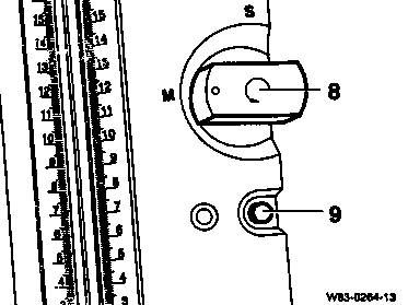
9 Turn rotary knob (8) from position "S"
(= suction) to position "M"(= measurement).
10 Press red button (9) and hold down until the display fluid ceases to rise.

11 Release red button (9) and after approx.
10 seconds turn rotary knob (8) back again to position "S".
12 Read off CO2 measurement value on the scale (11).
B. With CO2 indicator

1 Indicator | |
2 Protective cap | |
3 Rubber connector piece | |
4 Rubber ball | |
5 Filter | |
6 Emission sensor | |
7 Valve | |
8 Scale |
Commercially available tool Company
CO2 indicator | Bruno Ihrig Technische Meßgeräte D-6054 Rodgau - Dudenhofen | |
Measuring CO2 emission value
Note
- If the emission values cannot be adjusted, the distance between the impeller and the blower housing is excessive. Adjust combustion blower (83-5557).
- Before the measurement, check the dessicator, replace dessicant if the blue pellets are light blue or beige.
- The CO2 value must be measured:
- after repairs to the burner.
- in the event of combustion irregularities.
1 Set the vehicle heating and vehicle blower to maximum.
2 Switch on heater unit.
After approximately 5 minutes, measure CO2 value.
In the meantime, prepare the measuring unit.
Note
- After using the CO2 indicator, push the protective cap onto the valve.
- Change the measuring fluid (15% caustic potash solution - dyed red) and the filter wool after a maximum of 300 measurements or after 6 months at the latest.
- The chemicals must be disposed of as special waste in accordance with § 2 of the Federal Waste Law.

3 Turn the CO2 indicator through 180° and allow the measuring fluid to flow through the hollow glass body.
4 Turn CO2 indicator back through 180°
(= basic position) and allow the measuring fluid to flow back.

5 Remove protective cap (2).
6 To bleed the CO2 indicator, press the valve (7) several times.
Measuring
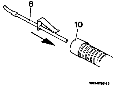
7 Introduce emission sensor (6) into the exhaust pipe (10).

8 Fit the rubber connector piece (3) of the suction device on the valve (7) and press down firmly.
Note
The rubber connector piece (3) must be pressed on to the valve (7) using one hand throughout the measurement, in order to ensure a tight connection.
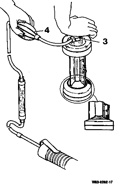
9 Sgueeze rubber ball (4) 18 times using the other hand.

10 Then rapidly detach the rubber connector piece (3) from valve (7) in order to avoid the emission specimen escaping.

11 Turn CO2 indicator four times through 180° in order to conduct the measuring fluid through the emission specimen.
Note
For each rotation, all the measuring fluid must flow through the CO2 indicator.
12 Position measuring equipment upright and after 10 seconds read off the CO2 content of the exhaust specimen on the scale.
Note
- In order to ensure an accurate measurement result, the supporting surface for the CO2 indicator must not be colder than 10°C.