47-030 Function of fuel tank breather and vent
Filler cap

1 | Filler cap |
2 | Sealing ring |
3 | Locking bar |
4 | Compression spring |
5 | Filler neck |
The fuel evaporation gases can escape through the filler cap at a pressure of 100-300 mbar gauge. This only occurs, however, if e.g. the passage in the vent line from the fuel tank is not clear. If the system is operating properly, an overpressure of up to 50 mbar may occur in the fuel tank.

50 | Fuel tank |
51 | Vent valve |
51/1 | Protective rubber boot |
54 | Central pipe |
54/1 | Interrupt vessel |
64 | Vent line |
The vent system consists of a central pipe (54) with an interrupt vessel (54/1) at each end.
The interrupt vessels prevent fuel escaping along the vent line. The vent line (64) runs from the central pipe to the vent valve (51).

If an overpressure of 30-50 mbar is reached in the fuel tank, the vent valve (4) opens and the fuel vapors flow to the charcoal canister.
1 Compression spring
2 Valve housing
3 Spring plate
4 Vent valve
5 Valve plate
6 Air admission valve
7 Connection fitting

If a vacuum of 1-16 mbar is produced in the fuel tank, the air admission valve (6) opens.

The protective rubber boot at the end of the vent valve prevents dirt and splash water entering the vent valve.
Standard implementation:
Model Vehicle ident No.
April 1986 May 1986
124 A 231133 F 050005
201 A 296211 F 227064
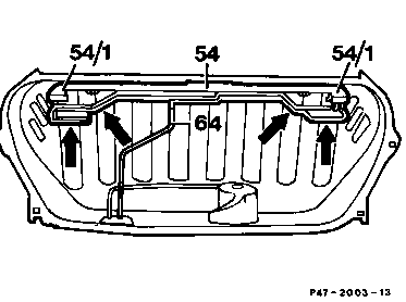
Vent system modified
The vent system has been modified by the addition of lines and interrupt vessels (arrows) so that no fuel can escape through the vent system even in extreme conditions (rollover).
Standard implementation: phased-in (approx. 10/88)
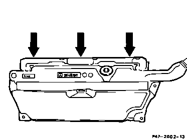
Model 201, plastic tank
The plastic tank is shaped in the top half (arrows) in such a way as to produce the function of the vent system (central pipe).