46 - 4079 Dismantling and assembling power steering pump
Preceding work: Power steering pump removed (46.2 - 4000). |
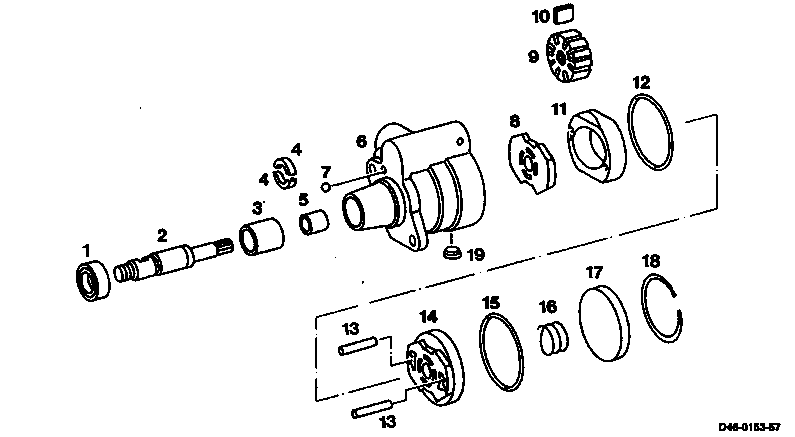
A LuK (Vickers) VT 51 power steering pump 51
D46-0153-57
1 Sealing ring Replace, fill with high-melting | 10 Pump vane |
point grease. | 11 Inner cam insert |
2 Drive shaft Do not remove. | 12 Sealing ring Replace. |
3 Plain bearing Do not remove. | 13 Pins |
4 Split bearing shells Do not remove. | 14 End plate |
5 Plain bearing Do not remove. | 15 Sealing ring Replace. |
6 Pump housing | 16 Spring |
7 Balls Do not remove. | 17 Cover |
8 End plate | 18 Snap ring |
9 Rotor | 19 Sealing plug Do not remove. |

Dismantling
-------------------------------
1 Using a thin drift through the side bore (arrow) in pump housing, press snap ring (18) out of the groove and remove.
D46-0154-13

2 Lever out cover (17) using pliers.
Note
- Loosen canted cover (17) by removing the paint coating in the area of the housing bore and by applying light jarring blows to the pump housing with a plastic hammer.
- Do not damage sealing surfaces.
D46-0155-13

3 Remove spring bracket (16) and end plate (14).
D46-0156-13

4 Tip out inner cam insert (11) and rotor (9) on to a soft surface.
D46-0157-13

5 Remove pump vane (10) from rotor (9).
Note
- Check pump vane (10) for scores and wear, primarily on the rounded off contact surface (arrow).
- Check rotor (9) for wear in the guide slots.
D46-0158-13
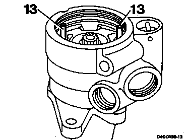
6 Pull out pins (13).
D46-0159-13
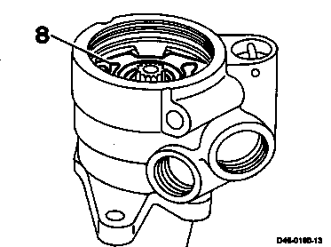
7 Lift out end plate (8).
D46-0160-13
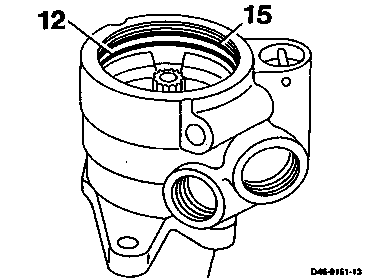
8 Remove sealing ring (12, 15).
D46-0161-13

9 Remove sealing ring (1).
D46-0162-13
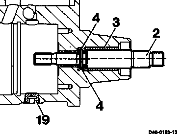
10 Check drive shaft (2) for play and ease of movement, if play is excessive or it is difficult to move, replace power steering pump.
- Installation/removal of drive shaft results in the destruction of the split bearing shells (4) and plain bearing (3). They are not available as parts.
- Sealing plug (19) is bonded and must not be unscrewed.
D46-0163-13
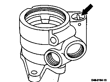
11 Remove pressure and flow control valve (arrow) (46.2 - 4223/1).
D46-0164-13
Assembly
-------------------------------
Note
- Prior to assembly, all bores in the pump housing must be blown out with compressed air. Clean all parts, lightly coat with oil and replace all sealing rings.
- Check all parts for visible wear and shrinkage.
- In the event of wear and scuffing points only replace inner cam insert, rotor and pump vane together.
- Check drive shaft in the installed condition for shrinkage of the sealing ring, replace power steering pump if required.
1 Install pressure and flow control valve (arrow) (46.2-4223/1).
D46-0164-13
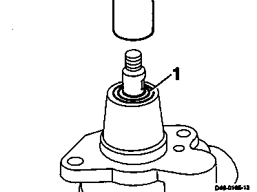
2 Pack sealing ring (1) between sealing lips with high-melting point grease and press in up to the stop using a suitable alignment tool.
D46-0165-13

3 Insert pins (3).
D46-0166-13
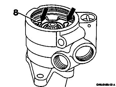
4 Insert end plate (8).
Note
Oil ducts (arrows) must point towards the cover.
D46-0160-13 A

5 Install inner cam insert (11). Install the bore with elongated hole (arrow) over pin (13).
D46-0167-13

Note
In the case of the inner cam insert (11), the marking (arrow) must point towards the cover.
D46-0168-13
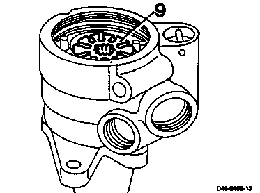
6 Install rotor (9).
Note
Chamfer on inside diameter of rotor (9) must point to the drive side.
D46-0169-13
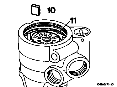
7 Install pump vane (10) with the rounded off surfaces towards the inner cam insert (11).
D46-0171-13

8 Install new sealing ring (12).
D46-0172-13

9 Install end plate (14). The two smaller recesses (arrows) must be inserted over the pins (13) in the pump housing.
D46-0173-13
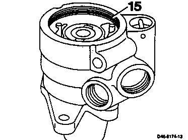
10 Install new sealing ring (15).
D46-0174-13
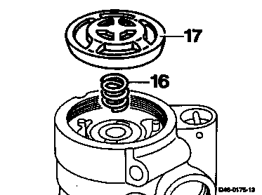
11 Place spring (16) on the end plate. Install cover (17) with the rounded off side inwards.
D46-0175-13

12 Press in cover until the snap ring (18) deflects.
Note
Deflect snap ring (18) so that the end is offset by approx. 2-3 cm, dimension "a", to the small bore (arrow) in the pump housing.
13 Install power steering pump (46.2 - 4000).
D46-0154-13 A
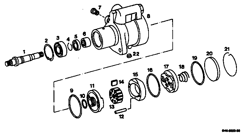
B ZF 7673 power steering pump
D46-0223-55
1 Drive shaft | 10 Sealing ring Replace. |
2 Circlip | 11 End plate on drive side |
3 Ball bearing | 12 Pin |
4 Snap ring Replace. | 13 Rotor |
5 Sealing ring Replace, pack | 14 Pump vane |
sealing lips | 15 Inner cam insert |
with high-melting | 16 Sealing ring Replace. |
point grease. | 17 End plate on cover side |
| 18 Spring |
6 Needle bearing | 19 Sealing ring Replace. |
7 Throttle insert | 20 Cover |
8 Pump housing | 21 Snap hook |
9 Sealing ring Replace. | 22 Sealing plug Do not unscrew. |
. |
Shop-made tools (if required)
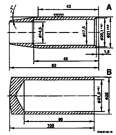
Device
for removal and installation of snap ring on drive shaft.
Material:
A Sleeve St 50
B Bush C 60 tempered
Round off edges.
D46-0145-15
-

Dismantling
-------------------------------
1 Remove snap hook (21) from pump housing.
D46-0224-13

2 Remove cover (20) and spring (18) from pump housing.
Note
- Loosen canted cover (20) by removing the paint coating in the area of the pump housing bore and by applying light jarring blows to the pump housing with a plastic hammer.
- Do not damage sealing surfaces.
D46-0225-13
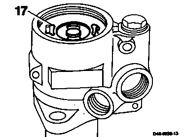
3 Withdraw end plate (17) from the pump housing.
D46-0226-13

4 Tip inner cam insert (11) and rotor (9) out of housing.
D46-0227-13
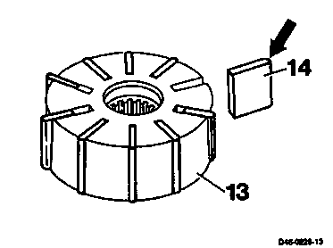
5 Remove pump vane (14) from rotor (13.
Note
- Check pump vane (14) for scores and wear, primarily on the rounded off contact surface (arrow).
- Check rotor (13) for wear in the guide slots.
D46-0228-13

6 Remove pin (12).
D46-0229-13
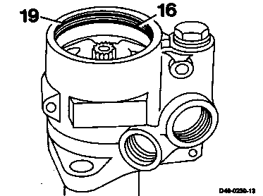
7 Remove both sealing rings (16, 19).
D46-0230-13
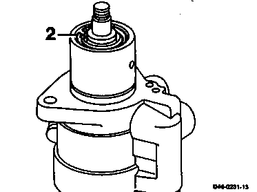
8 Remove circlip (2) on drive shaft.
D46-0231-13
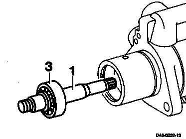
9 Press drive shaft (1) with ball bearing (3) out of pump housing.
D46-0232-13
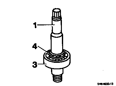
10Remove snap ring (4) from drive shaft (1). Press off ball bearing (3).
When removing snap ring (4) ensure that the contact surface of sealing ring on the drive shaft (1) is not damaged. If required remove with sleeve (A).
D46-0233-13

11 Press end plate out of housing using a soft drift.
12 Remove sealing ring (10) from the end plate (11).
D46-0234-13
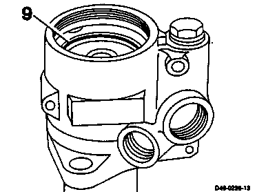
13 Remove sealing ring (9).
D46-0235-13

14 Press needle bearing (6) together with the sealing ring (5) out of pump housing.
Note
Prior to removal of needle bearing, measure the installed depth: dimension "a".
D46-0236-13
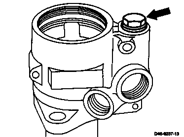
15 Remove pressure and flow control valve (arrow) (46.2 - 4223/4).
D46-0237-13

Sealing plug (22) and throttle insert (7) are bonded and must not be removed.
D46-0238-13
Assembly
-------------------------------
Note
- Prior to assembly, all bores in the pump housing must be blown out with compressed air. Clean all parts, lightly lubricate with oil and replace all sealing rings.
- Check all parts for visible wear and evidence of shrinkage.
- In the event of wear and scuffing points only replace inner cam insert, rotor and pump vane together.
- Check drive shaft for evidence of shrinkage of the sealing ring, ball bearing and needle bearing, replace all parts together, if required.

1 Install pressure and flow control valve
(46.2 - 4223/4).
D46-0152-13 A
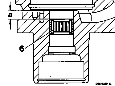
2 Press new needle bearing (6) into pump housing using suitable alignment tool.
Note
Note installed depth measured during removal:
dimension "a"
D46-0239-13
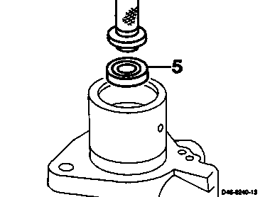
3 Pack new sealing ring (5) between sealing lips with high-melting point grease and press in up to the stop.
Note
Install sealing ring (5) so that the reinforced casing points to the drive side (side with inscription towards inside of housing).
D46-0240-13
4 Install new sealing ring (9) in pump housing.
D46-0235-13
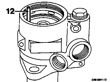
5 Insert pin (12) into pump housing.
D46-0241-13

6 Install new sealing ring (10) in the end plate (11).
D46-0242-13
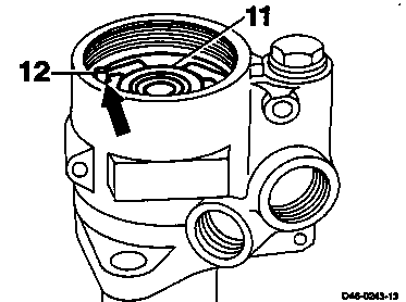
7 Push end plate (11) with the recess (arrow) over the pin (12) and press into the pump housing bore.
D46-0243-13

8 Press ball bearing (3) on to drive shaft (1).
D46-0244-13
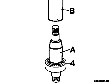
9 Install new snap ring (4).
Note
If required, push sleeve (A) on to drive shaft, install snap ring (4) with bush (B). Remove bush (B) and sleeve (A).
D46-0245-13
10 Press drive shaft (1) into pump housing until the ball bearing (3) contacts the stop.
D46-0232-13
11 Install circlip (2).
D46-0231-13
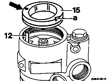
12 Install inner cam insert (15). Insert the bore (arrow) over the pin (12).
Note
The half arrow (a) cast on the edge of the inner cam insert (15) must point towards the cover.
D46-0146-13
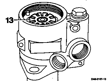
13 Install rotor (13).
Note
Chamfer on inside diameter of rotor (13) must point towards the drive side.
D46-0147-13

14 Install pump vane (14) with rounded off surfaces towards inner cam insert (15).
D46-0148-13

15 Install new sealing ring (16) in pump housing.
D46-0149-13
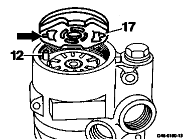
16 Install end plate (17). The smaller recess (arrow) must be inserted over the pin (12) in the pump housing.
D46-0150-13
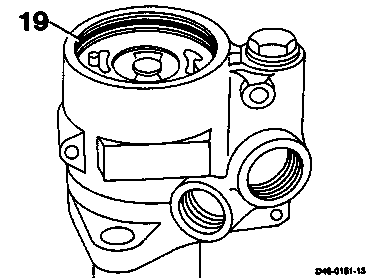
17 Install new sealing ring (19) in the pump housing.
D46-0151-13
18 Place spring (18) on the end plate. Position cover (20) with the chamfer inwards and press into the pump housing until the snap hook can be installed.
D46-0225-13

19 Install snap hook (21).
Note
The snap hook opening (arrow) must point towards the pressure and flow control valve be replaced.
20 Turn drive shaft and ensure easy smooth operation.
21 Install power steering pump (46.2 - 4000).
D46-0224-13 A