42 - 0845 Removal and installation of hydraulic unit
|
Tightening torque Nm
Retaining screw of brake line to hydraulic unit |
14 |

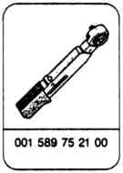
Special tools

Removal
1 When the ignition is switched off, disconnect ground cable at the battery.
2 Fold up front-end grill and support.
(Only on diesel vehicles.)
3 Detach brake lines from hydraulic unit. Seal connections and lines with blind plugs.
Caution
The hexagon socket bolts must not be slackened.

4 Unscrew fixing screw for cover.
Remove cover.

5 Disconnect ground strap at pump motor.

6 Unlock locking device for multiple plug. Detach plug.
Note
The two relays for the pump motor or for the solenoid valves can be exchanged.
Examine connection plug and cable for contamination or corrosion and clean thoroughly, if required.

7 Unscrew hexagon nuts and remove hydraulic unit from bracket.
Only store hydraulic unit upright.
Installation
1 Install hydraulic unit in the bracket and secure with hexagon nuts.
2 Connect ground strap to pump motor.

3 Connect brake lines to the hydraulic unit and tighten using . (14 Nm)
Caution
Brake lines must not be confused
001 589 75 21 00
000 589 75 03 00
Diagonal brake circuit split
1.1 = from brake master cylinder, plunger circuit
1.2 = from brake master cylinder, intermediate piston circuit
2.1 = to left front wheel brake
2.2 = to right front wheel brake
2.3 = to right rear wheel brake
2.4 = to left rear wheel brake

4 Fit multiple plug. Engage locking device.
5 Secure cover on hydraulic unit.
Note
To prevent the penetration of splash water via the connection cable, route this to the hydraulic unit in a curve from underneath and also fasten to the ground connection of the pump motor using a cable tie.
6 Close front gate and secure.
7 Bleed brake system and check for leaks.
(42 - 0016)
8 Connect ground cable to battery.
9 Perform test program. (Refer to Diagnosis Manual - Transporter T1/T2 volume 1)