29.5-055 Removal and installation of bearing bracket (pedal unit)
Preceding work: Combination switch removed Steering lock removed |
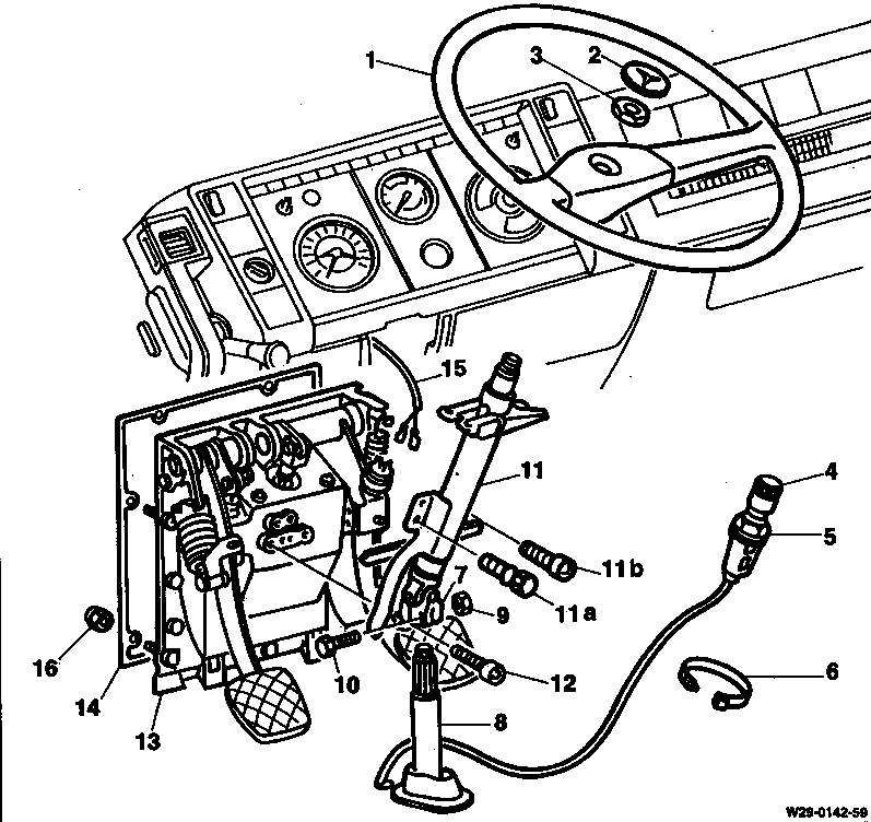
1 | Steering wheel | Puller 355 589 00 33 00 |
2 | Trademark | |
3 | Hexagon nut | 55 Nm. |
4 | Idle speed adjuster | |
5 | Hexagon nut | |
6 | Cable straps | Replace. |
7 | Universal joint | |
8 | Steering shaft | |
9 | Hexagon nut | 30 Nm. |
10 | Hexagon bolt | 30 Nm. |
11 | Steering shaft | |
11a | Breakaway bolt | Replace. |
11b | Hexagon socket bolt | |
12 | Hexagon socket bolt |
13 | Bearing bracket | |
14 | Gasket | Replace. |
15 | Plug connection, stop lamp switch | |
16 | Hexagon nut | 20 Nm. |
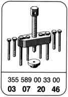
Special tool

Removal and installation
1 Remove left-hand foot mat and steering shaft trim.
2 Remove trim above the pedals.
3 Lift out trademark (2) in steering wheel using a small screwdriver.

4 Unscrew hexagon nut (3).
Installation note
Securely tighten hexagon nut, 55 Nm.

5 Detach steering wheel.
Puller 355 589 00 33 00

Installation note
Place steering wheel on the steering shaft spline so that the markings (arrows) align.

6 Loosen hexagon nut (5) on idle speed adjuster (4).
7 Remove cable straps on the steering shaft and detach idle speed adjuster from the steering shaft.

8 Mark position of universal joint (7) in relation to steering shaft (8).
9 Unscrew self-locking hexagon nut (9) on universal joint and withdraw hexagon bolt (10).
Installation note
Securely tighten new self-locking hexagon nut (9), 30 Nm.

10 Unscrew breakaway bolt (11a) and hexagon socket bolt (11b).
Installation note
Securely tighten new breakaway bolt (11a) and shear off.
11 Unscrew hexagon socket bolts (12).
12 Remove steering shaft (11) on bearing bracket.
Installation note
When installing universal joint (7) over the steering shaft (8), observe the marking.

13 Open maintenance flap.
14 Extract hydraulic fluid from the reservoir (19).
15 Detach reservoir (19) from master cylinder (20).

16 Unscrew hydraulic pipe (21) on master cylinder (20).

17 Unscrew compressed-air pipes (22) and vent pipe (23) on brake valve.

18 Disconnect 2-pin plug connection (15) on stop lamp switch (18).

19 Unscrew hexagon nuts (16) and remove bearing bracket (13) inwards.
Installation note
Securely tighten hexagon nuts (16), 20 Nm.

20 Remove gasket (14).
Installation note
Stick new gasket (14) on bearing bracket (13).
21 Install in reverse sequence.
22 Bleed hydraulic clutch control (29.3-030).
23 Adjust lost motion of hydraulic clutch control
(29.5-010).
24 Adjust lost motion of brake control
(29.5-035).
25 Adjust stop lamp switch (29.5-050).