27-640 Dismantling and assembling transmission
Operation number of the operation texts and work units or standard texts and flat rates: 27-4010 |

P27-2407-13
Dismantling brake band plunger
Remove brake band plunger from plunger cover.
Spread locking device (40a) in brake band plunger cover (40) using circlip pliers and remove pin (37c). Leave the locking device in the brake band plunger cover.
Remove snap ring (illustration 3, item 37b) in brake band plunger using a screwdriver; then remove disk spring.
Illustration 2

P27-2408-13
Assembling brake band plunger
Insert pin (37c) in brake band plunger.
Note installed position.
Push disk spring (37a) over pin until it contacts the brake band plunger; note installed position. Insert snap ring (37b). Ensure that it is correctly seated.
Press assembled brake band plunger into plunger cover until it locks in position audibly. Do not pull it apart by hand once it has locked.
Install assembled brake band plunger; it adjusts itself automatically.
Illustration 3

P27-2065-13
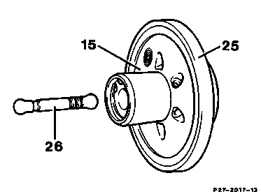
122 Insert pressure pin thrust bearing B2 (28) with larger diameter pointing towards brake band B2 (27).
P27-2017-13
123 Insert teflon ring (25) into groove with grease.
Note
Introduction of improved teflon ring (molded T-ring) as of transmission no. 3 915 083
124 Insert pressure pin (26)
Note
Pressure pins (26) are available in lengths of 47.2, 48.0, 48.8 and 49.6 mm for correcting the idle travel at brake band B2.

P27-2083-13
125 Introduce brake band plunger B2 (15) ensuring that pressure pin (26) engages in brake band.

P27-5335-35
Repair note for reconditioned transmission
Phased in as of 06/94 the bore for supporting plunger B2 is reworked after wear limit is reached. This necessitates a modified sealing ring with a larger diameter for plunger B2.
The housing is identified by engraving "89 dia.".
Note
Only the modified sealing rings may be installed when repairing reconditioned transmissions, the housings of which are identified with the diameter specifications (89).

P27-2081-13
126 Press in brake band plunger cover B2 (17) and insert circlip (23).
P27-2015-13
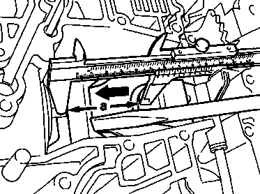
127 Measure clearance "L" at brake band B2 and adjust.
Press brake band B2 (27) by the support tab towards the brake band plunger (in direction of arrow) so that brake band plunger rests against brake band plunger cover. Measure distance "a" at brake band using caliper gauge.
P27-2014-13
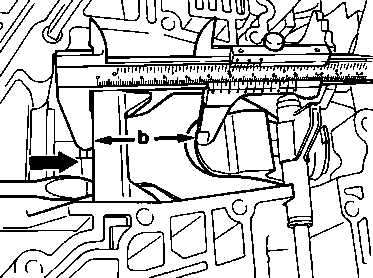
Similarly, press brake band B2 (27) by the support tab towards the thrust element (in direction of arrow).
Measure distance "b".
The difference between measurements "a" and "b" is equal to the clearance "L".
Adjust clearance "L" to 5.5 - 5.7 mm by replacing the thrust pin (26) at brake band plunger B2.

P27-2082-13
128 Insert brake band guide B2, one-way valve (49), filler element (128), locating pin (135), temperature restrictor (117) and oil deflector (119) in transmission housing.

P27-2034-13
129 Assemble lower cover (13) with intermediate plate (14) (27-430).
Attach lower cover with intermediate plate ensuring that the oil pipe (9) is inserted into the bore (arrow).

P27-2038-13
130 Center intermediate plate (14) with two bolts (7).
131 Insert bolts with washers (8) and tighten to 8 Nm.
132 Attach leaf spring (142) with bracket (141) and tighten bolt (140) to 8 Nm.
Note
Ensure that the locating pin for the brackets (141) is correctly inserted.
P27-2016-13
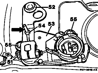
133 Mount range selector lever (52) so that the driver (54) is located in the range selector lever.
134 Insert hexagon bolt (51) and tighten to 8 Nm.
135 Move range selector lever (52) to position "N", insert a 4 mm cotter pin (arrow) through the range selector lever into the locating bore of the shift housing and tighten hexagon bolts (55) to 8 Nm. Then remove cotter pin.

P27-2036-13
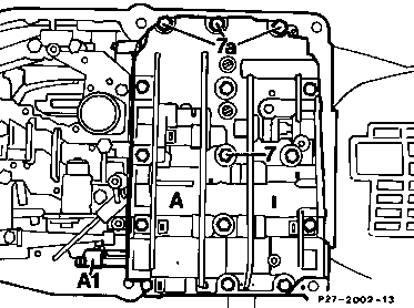
136 Attach shift valve housing (A), ensuring that the range selector lever (A1) enguages in the driver on the notched plate (arrow).
P27-2002-13
137 Insert bolts with washers (7) and tighten to 8 Nm.
Note length of bolts. The three bolts marked with item no. 7a are only 50 mm, the remaining 12 bolts are 55 mm long.

P27-0104-13
138 Check play "a" between locking plunger (122) and stop on spring linkage (82), and adjust if necessary.
The play "a" is adjusted to 0.4 - 1.0 mm in position "N" by means of the plastic clip (118). The plastic clip is available in two thicknesses.

P27-2039-13
139 Check O-ring on control pressure cable and renew if necessary, then attach control pressure cable onto connecting rod (110). Insert limiting rod (111) into bore (arrow) and insert control pressure cable.
140 Turn control pressure cable until it locks in place.
P27-2004-13
141 Attach oil filter and tighten cross-head bolts
to 4 Nm.
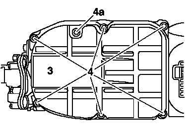
142 Attach oil pan (3) and tighten retaining bolts
(4) to 8 Nm.
P27-2005-13
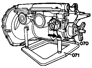
143 Remove bolt (arrow) and lift transmission out of assembly unit.
After installation, check transmission for leaks and also check modulating pressure and adjust if necessary.