26 - 4860 Mainshaft - Dismantling and assembly
|
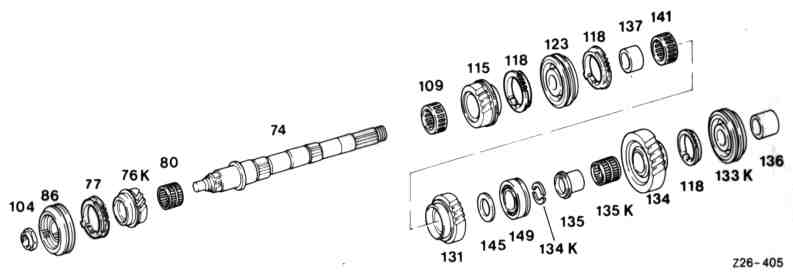
Z26-405
74 Mainshaft 133K 1st/reverse gear synchronizer body
76K 4th gear 134 1st gear
77 4th/5th gear synchronizer 134K Split ring half
80 Needle bearing check 135 Bushing
86 4th/5th gear synchronizer body 135K Needle bearing check
104 Nut 120 Nm 136 Shim
109 Needle bearing check 137 Shim
115 3rd gear 141 Needle bearing check
118 1st/2nd/3rd gear synchronizer ring 145 Thrust washer
123 2nd/3rd gear synchronizer body 149 Cylindrical roller bearing check
131 2nd gear
Data
Mainshaft installation dimension | 2240.1 |
Synchronizer ring wear limit | 0.5 |
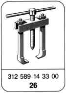
Special tool

Dismantling
-------------------------------
1 Clamp mainshaft in position (use device with soft jaws). Unlock 6-point nut and unscrew.
D26-0104-13

2 Remove entire 4th/5th gear synchronizer body from the mainshaft.
D26-0105-13
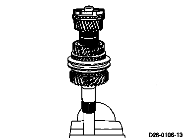
3 Remove 4th gear together with synchronizer ring and needle bearing.
D26-0106-13
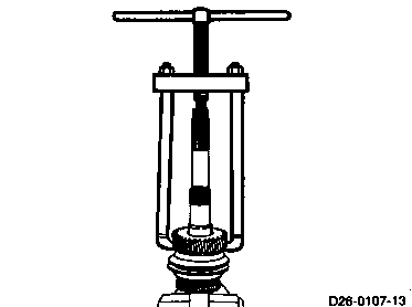
4 Turn mainshaft to other side. Pull off 2nd gear, thrust washer and inner race of roller bearing.
D26-0107-13

5 Remove needle bearing and synchronizer ring.
6 Press 3rd gear, 2nd/3rd gear synchronizer body and the 2nd gear spacer ring from the mainshaft as a single unit.
7 Remove needle bearing from mainshaft
D26-0108-13

8 Inspect all components, noting both general condition and any particular signs of wear.
9 Place the synchronizer rings on their respective helical gear cones, then use a feeler gauge to determine the gap between the teeth of the synchronizer ring and those of the helical gear.
Note:
The synchronizer rings reach their wear limit at a gap of 0.5 mm. The synchronizer ring must then be replaced (also watch for wear on the helical gear cones).
D26-0074-13
Main shaft, rear - Measurements and assembly
-------------------------------
Note:
Carry out the operations described in
Positions 9 - 19 only when previous work makes it necessary to remeasure and readjust the mainshaft assembly, for instance, when the bearings are replaced.
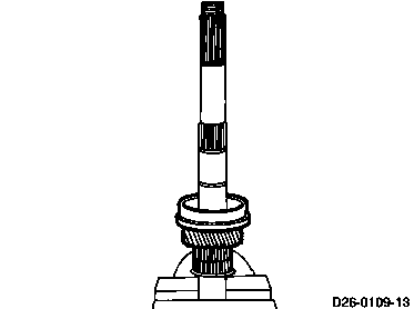
1 Clamp mainshaft in position (use soft jawed clamping device).
2 Slide needle bearing and 3rd gear onto the mainshaft.
D26-0109-13

3 Position synchronizer ring.
4 Slide the 2nd/3rd gear synchronizer body onto the mainshaft with the shift sleeve shoulder toward 2nd gear.
D26-0110-13

5 Heat the spacer shim for 2nd gear to ca. 100°C and slide it onto the mainshaft.
D26-0111-13

6 Place the synchronizer ring on the synchronizer body. Slide needle bearing and 2nd gear onto the mainshaft.
D26-0112-13

7 Position the previously-installed thrust washer (1) with the smooth side toward the gear.
Note:
The thrust washer should be sufficiently thick that the bearing race protrudes somewhat from the mainshaft recess.
8 Heat the bearing inner race to approx. 100°C and slide it over the mainshaft.
D26-0113-13

9 Insert the split ring in the mainshaft recess.
D26-0114-13

10 Heat the bushing for 1st gear to approximately 100°C and slide it on. Use a suitable sleeve to drive it on until contact is achieved.
D26-0115-13

11 Slide needle bearing and 1st gear onto the bushing.
D26-0116-13

12 Put the synchronizer ring on 1st gear.
13 Push the 1st/reverse gear synchronizer body onto the mainshaft with the shoulder toward reverse gear.
D26-0117-13

14 Heat the reverse gear spacer ring to approximately 100°C and slide it onto the mainshaft.
D26-0118-13

15 Slide the correct spacer sleeve onto the mainshaft, then use the groove nut to tighten down the mainshaft assembly. Once the mainshaft has cooled, remove the groove nut and spacer sleeve.
D26-0119-13
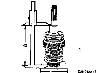
16 Use calipers to measure the distance between the mainshaft collar and the reverse gear spacer ring.
Specified distance: 224 0.1 mm
17 Install the correct thrust washer (1) to achieve the specified distance between 2nd gear and the bearing race.
D26-0120-13
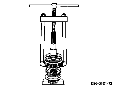
18 Pull 1st gear, the synchronizer body and the spacer shim from the mainshaft.
D26-0121-13

19 Pull off the 1st gear bushing. Remove the split ring.
D26-0122-13

Mainshaft, front - Assembly
-------------------------------
1 Slide needle bearing and 4th gear onto the mainshaft.
2 Install synchronizer ring.
D26-0123-13
3 Slide the 4th/5th gear synchronizer body onto the mainshaft with the wide hub side pointing toward 4th gear. The groove in the shift sleeve must be toward 4th gear.
D26-0106-13

4 Tighten down and lock 6-point nut.
D26-0124-13