03-6311 Mounting conrod in bearings
Preceding work: Pistons removed (03-7081). |

1 Conrod 3 Conrod bearing cap 4 Conrod bolts 5 Conrod bearing shells | see data "A". oil with engine oil; oil with engine oil, |
Data "A" conrod
Basic bore diameter in conrod
Overlap of the conrod bearing shells 0.04 to 0.07
Radial play of the conrod bearing journals 0.041 to 0.100
Axial play of the conrod bearing journals 0.100 to 0.400
Permissible deviation in axial parallelism of the conrod 0.010
Permissible out-of-roundness of the basic bore for
the conrod bearings and conrod bush 0.005
Parallelism of the bearing surfaces 0.017
Distance from center crankshaft 230.05
to center piston pin bore 230.00
Width of conrod at 37.830
conrod bearing eye 37.730
Permissible difference in weight of conrods within an engine 40 g
65.019
65.000
Data "B" (conrod bearing shells) | ||||||
Standard | Deviation 0.1 | Deviation 0.25 | Deviation 0.5 | Deviation 0.75 | Deviation 1.0 | |
Diameter of | 60.015 59.995 | 59.915 59.895 | 59.765 59.745 | 59.515 59.495 | 59.265 59.245 | 59.015 58.995 |
Bearing bore | 60.095 60.056 | 59.995 59.956 | 59.845 59.806 | 59.595 59.556 | 59.345 59.306 | 59.095 59.056 |
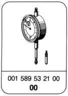
Special tool

Seating conrods
1 Use a chamois leather to clean the bearing points in the conrod and in the conrod bearing caps.
Note
New conrod bearing shells are factory-supplied ready for installation. Machining work on the conrod bearing shells is not permitted.
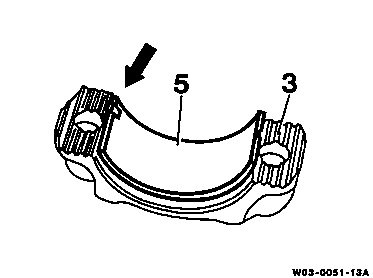
2 Install conrod bearing shells (5) into conrod and conrod bearing cap. Ensure that the lugs of the conrod bearing shells are located in the slots of the basic bore.

3 Measure conrod bolts (4), max. shank length 56.8 mm.
Note
Apply a light coating of engine oil to the thread of the conrod bolts (4).

4 Mount conrod bearing cap (3) together with conrod bearing shell onto the conrod (1), observing the marking (arrows) (numbers must be located on one side).
5 Screw in conrod bolts (4).
Note
Clean threads of blind holes in the conrod (1).

6 Tighten conrod bolts (4),
1st stage 40 to 50 Nm;
2nd stage 90° to 100° angle of rotation.

7 Set 50 - 100 mm diameter hole gauge with 50 - 75 mm diameter micrometer to the zero size of the main bearing bore.
Dial gauge 001 589 53 21 00

8 Measure main bearing bore with the set 50 - 100 mm dia. hole gauge at three points (vertical and at about 30° above and below the separation points).
Note
The measurements must conform to the figures stated in data "B".
Dial gauge 001 589 53 21 00
9 Remove bearing cap (3) again.
Odkazované dokumenty
- bb0040p022302a Přehled předepsaných motorových olejů pro osobní, dodávková vozidla (servis)
- ra00333640002x
- ra00333640004x
- ra00333640005x
- ra00333640010x
- ra00333640901x
- ra03333647081x