03-4801 Removing and installing crankshaft gear
Preceding work: Oil sump removed (01-7500) Timing case cover removed (01-8000). |
Data
Gear backlash 0.070 to 0.180 mm
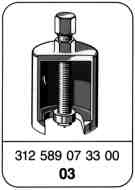
Special tool
A Divided timing case
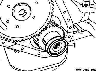
Removing, installing
1 Remove oil seals.
Installation note
Coat oil seal (1) with engine oil.

2 Remove lower section of timing case (2).
Installation note
- Coat contact surface (arrows) of lower section of timing case (4) with Curil T sealant.
- Coat hexagon bolt M840 (5) on thread with Hylomar SQ 32M sealant.
- Screw on lower section of timing case with hexagon bolts M840 (5) and M822 (6) onto timing case.

3 Pull off crankshaft gear (3) from crankshaft.
Puller 312 589 07 33 00

Installation note
- Heat crankshaft gear (3) to approx. 80°C.
Risk of burns.

- Assemble crankshaft gear (3) over woodruff key (4).
Note
The tooth of the crankshaft gear (3) marked with "1" must be located between the teeth of the injection timer which is also marked with "1-1".

4 Use pliers to remove woodruff key (4).
5 Install in reverse order.
B One-piece timing case

Removing, installing
1 Remove kidney-shaped cover (5) at the timing case.
Installation note
- Install kidney-shaped cover (5) with new gasket (6).
- Seal hexagon bolts (7) with Hylomar SQ 32M sealant.

2 Crank engine in direction of rotation until the marking of the injection timer and crankshaft are aligned.
Note
The tooth of the crankshaft gear marked with "1" must be located between the teeth of the injection timer which are also marked with "1-1". The markings must be in line with the center of the two gears.

3 Mark injection pump gear at timing case.
Installation note
Check marking between injection pump gear and timing case.

4 Unscrew securing bolt (8) for injection timer (9).
Installation note
- Tighten securing bolt (8), 300 Nm.
- Check backlash 0.070 - 0.180 mm.

5 Remove injection timer (9) and parallel key (10).
Installation note
The tooth of the crankshaft gear marked with "1" must be located between the teeth of the injection timer (8) which is also marked with "1-1". The markings must be in line with the center of the two gears.
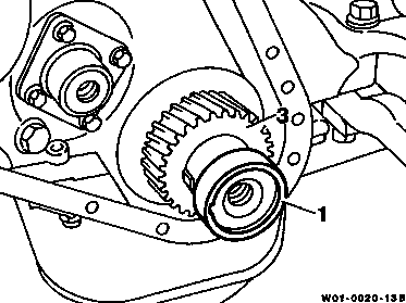
6 Remove oil seal (1).
Installation note
Coat oil seal (1) with engine oil.

7 Pull off crankshaft gear (3) from crankshaft.
Puller 312 589 07 33 00
8 Use pliers to remove woodruff key (4).

Installation note
Heat crankshaft gear (3) to approx. 80°C and assemble over woodruff key (4).
Risk of burns.
9 Install in reverse order.
Odkazované dokumenty
- bb0040p022302a Přehled předepsaných motorových olejů pro osobní, dodávková vozidla (servis)
- ra00333640002x
- ra00333640004x
- ra00333640005x
- ra00333640010x
- ra00333640901x
- ra01333647500x
- ra01333648000x