
S83.55-2003-06
Refrigerant compressor 7SB16C
1 Input shaft
2 Cylinder housing
3 Swash plate
4 Pistons
5 Valve plate
6 Inlet valve
7 Pressure control valve
8.1 Control valve
9 Spring
10 Transfer duct
11 Stop plate
Function
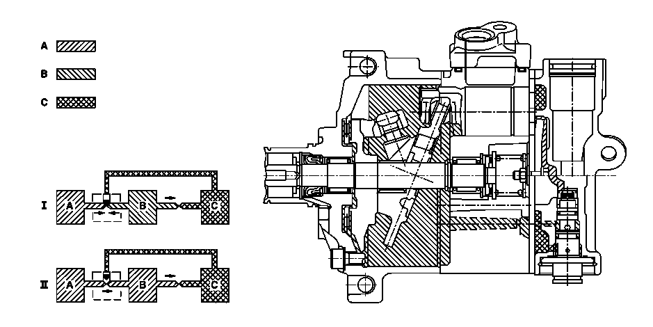
After the electromagnetic clutch (A9k1) has produced the frictional connection between the automotive engine and the refrigerant compressor, the drive shaft (1) drives the swash plate (3). The rotation of the inclined swash plate (3) causes the pistons (4) to move in strokes. During the intake stroke, refrigerant vapor is sucked in via the inlet valve (6).
If the piston (4) moves in the counter direction, it delivers the refrigerant vapor via the pressure control valve (7), with the vapor being compressed and heating up, into the refrigerant line to the capacitor. With refrigerant compressor, model 7SB16C, the refrigerant vapor acts on the control valve (8.1) in the refrigerant compressor for volume control.
Volume control in model 7SB16C
With a low engine speed, the efficiency of an air conditioning system is severely reduced by the low number of working strokes of the refrigerant compressor and the reduced cooling of the refrigerant in the capacitor. In this situation there is an increase in the thermal load. The refrigerant compressor is therefore designed so that it has a sufficient delivery rate even at low rotational speeds.
With an increase in the engine speed and the vehicle speed, the thermal load drops and the delivery rate of the refrigerant compressor increases. To prevent the refrigerant compressor now from consuming unnecessary engine power and nevertheless to maintain the refrigeration cycle, the refrigerant compressor reduces its power from a maximum of 100 % to a minimum
of 5 %.
S83.55-2004-09
Function
A = High pressure
B = Crankcase pressure
C = Manifold air pressure
100 % power (Ⅰ)
The conditions for full power are either a constantly low rotational speed or a high thermal load or both. The high manifold air pressure C causes the control valve to close. This prevents steam from flowing between the rear opening and the crankcase. There is always some flow through the transfer duct between the crankcase and the inlet opening. Therefore, in the crankcase there is almost the same pressure B as on the inlet side C. As a result, the swash plate is moved into the position for maximum volume. The angle between the swash plate and the vertical is at its greatest. This results in a large stroke.
Power from 100% to 5% output (Ⅱ)
If the influencing conditions change in that the thermal load drops or the engine speed increases, the pressure on the inlet side C drops and allows the control valve to open.
Then compressed refrigerant now flows from the rear opening to the crankcase. The pressure in the crankcase B increases therefore and causes the swash plate to reduce its angle, which leads to a reduction in power.

S83.55-2005-09
Function
A = High pressure
B = Crankcase pressure
C = Manifold air pressure
5% power (Ⅲ)
If the engine speed is high or the thermal load is low, this results in a constantly low manifold air pressure C which keeps the control valve open.
There is a flow from the high-pressure side A to the crankcase. The pressure in the crankcase B reaches a peak. Consequently, the swash plate is forced into a position in which only a minimum power is possible. The angle between the vertical and the swash plate is at its smallest. This results in a small stroke.
Power from 5% to 100% output (Ⅳ)
If the conditions change again in that the thermal load increases or the engine speed drops, the manifold air pressure C increases. There is now no longer any flow between the rear opening and the crankcase.
Due to the uniform flow from the crankcase to the inlet opening through the transfer duct, the high pressure A reaches almost the same level as the manifold air pressure C. Consequently, the swash plate angle increases and therefore the power increases until it reaches a maximum.