
P54.18-0203-75
up to 02/97
A1 Instrument cluster
N3/8 DFI control module
N19 Tempmatic air conditioning pushbutton control module (SA)
N22 Automatic air conditioning pushbutton control module (SA)
N15/3 ETC control module
N47-1 ASR/SPS control module (SA)
N47-2 ETS/SPS control module
N54 Remote central locking (RCL) control module
CAN Controller Area Network (CAN data bus)
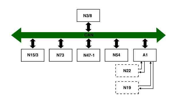
P54.18-0304-75
as of 03/97
A1 Instrument cluster
N3/8 DFI control module
N19 Tempmatic air conditioning pushbutton control module (SA)
N22 Automatic air conditioning pushbutton control module (SA)
N15/3 ETC control module
N47-1 ASR/SPS control module (SA)
N73 Electronic ignition switch EIS control module
CAN Controller Area Network (CAN data bus)
Task | Permitting the control modules to communicate with each other through a CAN data bus in order to achieve improved data transfer between the individual control modules. A side effect of this is a reduction in the extent of the wiring loom and thus an improvement in the electromagnetic compatibility of the entire electronic system. | ||
Design | The CAN data bus consists of a specially twisted two-core cable which is used for digital data transfer. The users (control modules) are linked to these cables. The so-called bus terminal (a 120 Ohms resistor) is also located at the particular terminal control module. A resistance measurement (ignition off!) between the two cables would produce 60 Ohms – twice 120 Ohms in parallel. A fault or failure within a control module does not affect operation of the CAN data bus provided the CAN interface element of the control module is not destroyed. If a control module is disconnected, the data bus is interrupted at both cores and is therefore no longer operational. | ||
Function | The data are transmitted at various intervals. A defined protocol determines how and when users transmit data. Each control module connected to the CAN data bus is capable of transmitting and receiving. The term bus in this case means that the data are not passed from one control module to the other but that the data are available simultaneously for all data bus users. The data are transferred digitally at various intervals. |