GF47.00-W-3012C | Fuel high pressure delivery, function | 18.12.03 |
ENGINE 541.9 in MODEL 950, 952, 953, 954
ENGINE 542.9 in MODEL 950, 952, 954

W07.15-1365-78
Shown on engine 541.9
1 Unit pump
2 High pressure pipe
3 Pressure pipe connection
4 Nozzle holder combination
A Fuel feed
(suction or vacuum side)
B Fuel feed
(thrust side)
C Fuel high-pressure
D Fuel return
Y6 Cylinder 1 unit pump
Y7 Cylinder 2 unit pump
Y8 Cylinder 3 unit pump
Y9 Cylinder 4 unit pump
Y10 Cylinder 5 unit pump
Y11 Cylinder 6 unit pump
General information
The fuel high pressure delivery for the PLD system is accomplished using individual unit pumps (1), each of which is assigned to one cylinder. The unit pumps (1) are driven by the camshaft via roller tappets and are connected to the injection nozzles in the nozzle holder combinations (4) via short high pressure lines (2) and the pressure pipe connection (3).
Each unit pump (Y6 to Y11) has a fast-acting solenoid valve. This solenoid valve regulates the start of delivery and controls the quantity delivered. The solenoid valves are actuated by the MR/PLD control unit that calculates the start of delivery and the quantity delivered according to the operating condition of the engine as soon as the engine is cranked and/or when the engine is running.
However, it is required that before actuation, the immobilizer (WSP) in the MR/PLD control unit detect a correct transponder code (from the ignition key) and be therefore deactivated. In addition, the engine stop push button switch must not be activated if the engine has been started with the engine start push button switch because in this case, even the solenoid valves have not been actuated.
Function
Depending on the position of the camshaft, each of the unit pumps (1) have the following power strokes:
Induction stroke
Pre-stroke
Delivery stroke
Residual stroke
Together these power strokes form a working cycle, which is repeated with every additional rotation of the camshaft at the respective unit pumps (1), till the engine is turned off.
As soon as the engine is switched off, the MR/PLD control unit stops the actuation of the solenoid valves. The unit pumps (1) pump the fuel virtually unpressurized into the fuel return for the low-pressure fuel circuit and the engine dies.
The description of one operating cycle of the unit pump of the 4th cylinder , given below, applies for all other unit pumps.

W07.15-1239-75
Induction stroke, illustrated on unit pump of the 4th cylinder on engine 541.9
1 Unit pump
2 High pressure pipe
3 Pressure pipe connection
4 Nozzle holder combination
5 Pump element
6 Supply passage
7 Solenoid valve
8 High pressure chamber
B Fuel feed
C Fuel high-pressure
D Fuel return
The induction stroke begins after the peak of the cam is exceeded and the pump element (5) moves downwards under the force of the restoring spring.
Owing to the continuous fuel overpressure of about 4 to 6 bar in the fuel low pressure circuit, the high-pressure chamber (8) is filled with fuel via the supply passage (6) and the opened solenoid valve (7).
Therefore, the pressure in the high-pressure chamber (8) filled with fuel is the same as the pressure in the fuel low pressure circuit.

W07.15-1236-75
Pre-stroke, illustrated on unit pump of the 4th cylinder on engine 541.9
1 Unit pump
2 High pressure pipe
3 Pressure pipe connection
4 Nozzle holder combination
5 Pump element
6 Supply passage
7 Solenoid valve
8 High pressure chamber
9 Return flow passage
B Fuel feed
C Fuel high-pressure
D Fuel return
After the induction stroke, the pump element (5) continues to remain in the low stop position, and the roller tappet of the unit pump (1) rolls off on the base circle of the unit pump cam. The pre-stroke begins only when the camshaft rotates further and the pump element (5) begins to move in the upward direction owing to the rising unit pump cam.
Due to the upward movement of the pump element (5) and the still open (de-energized) solenoid valve (7), initially forces the fuel in the high-pressure chamber (8) into a diversion chamber and then into the return flow passage (9).
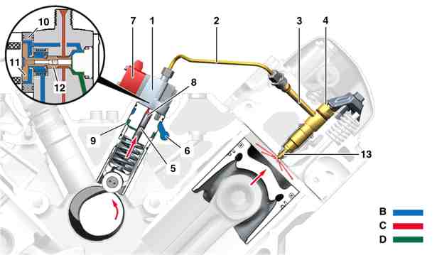
W07.15-1237-75
Delivery stroke, illustrated on unit pump of the 4th cylinder on engine 541.9*
1 Unit pump
2 High pressure pipe
3 Pressure pipe connection
4 Nozzle holder combination
5 Pump element
6 Supply passage
7 Solenoid valve
8 High pressure chamber
9 Return flow passage
10 Solenoid
11 Armature plate
12 Float needle
13 Injection nozzle
B Fuel feed
C Fuel high-pressure
D Fuel return
The pre-stroke concludes, and the delivery stroke begins as soon as the MR/PLD control unit actuates the solenoid (10) in the unit pump (1). The solenoid (10) activates the anchor plate (11) with the float needle (12), which then locks the connection between the high pressure chamber (8) and the return flow passage (9).
If the solenoid valve (7) is closed, the fuel in the high-pressure chamber (8) is compressed due to the upward movement of the pump element (5) (start of delivery).
With the further upward movement of the pump element (5), the pressure in the high-pressure chamber (8), and thereby the pressure in the high-pressure line (2), in the pressure pipe connection (3) and in the injection nozzle (13) also increases further.
At a pressure of about 330 bar, the injection nozzle (13) opens, and the fuel is injected into the combustion chamber (start of injection). The fuel pressure can rise up to 1800 bar during injection.
The unit pump (1) is in the delivery stroke as long as the pump element (5) moves in the upward direction, and the solenoid valve (7) is closed. The holding time of the solenoid valve (7) determines the quantity delivered and / or injected.

W07.15-1238-75
Residual stroke, illustrated on unit pump of the 4th cylinder on engine 541.9*
1 Unit pump
2 High pressure pipe
3 Pressure pipe connection
4 Nozzle holder combination
5 Pump element
6 Supply passage
7 Solenoid valve
8 High pressure chamber
9 Return flow passage
10 Solenoid
11 Armature plate
12 Float needle
13 Injection nozzle
B Fuel feed
C Fuel high-pressure
D Fuel return
If the actuation of the solenoid (10) is stopped, the float needle (12) of the solenoid valve spring is pushed back in its starting position on the shut-off stop. The solenoid valve (7), and thereby the connection between the high-pressure chamber (8) and the return flow passage (9) is opened. As a result, the fuel pressure in the high-pressure chamber (8) and in the injection nozzle (13) falls sharply. The injection nozzle (13) closes and the process of injection concludes (end of delivery).
The remainder of the fuel delivered by the pump element (5) up to the peak of the unit pump cam is again delivered to the fuel low pressure circuit through the diversion chamber and the return flow passage (9).
The diversion chamber is necessary as the expansion chamber for the pressure peaks of the unit pump (1) in the residual stroke. This prevents the pressure behavior of the adjacent unit pumps being affected through the return flow passage (9).