GF07.15-W-4004A | Determination of the compression stroke at cylinder 1, function | 4.7.07 |
ENGINE 904.9 in MODEL 375.1 with BODY 375.830
ENGINE 904.9 in MODEL 970, 972, 975, 976 with BODY 972.899
ENGINE 906.9 in MODEL 970, 972, 974, 975, 976 with BODY 972.899
ENGINE 906.9 in MODEL 375.3 with BODY 375.810
ENGINE 906.9, 926.9 in MODEL 950, 952, 953, 954 with BODY 940.899
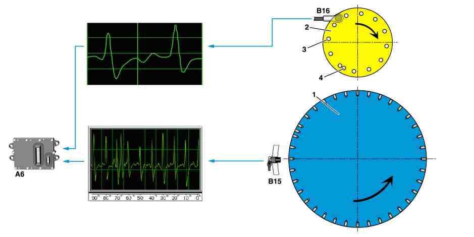
W07.15-1343-79
1 Flywheel
2 Camshaft sprocket
3 Bores - to detect the engine speed (only where required)
A6 MR/PLD control unit
B15 Crankshaft angle position sensor
B16 Cylinder 1 TDC sensor
4 Additional bore - for detecting the compression cycle at cylinder 1)
General information
Detection of the compression cycle at cylinder 1 takes place as soon as the engine has started. Since the position of the crankshaft alone is not sufficient, the engine control (MR) also uses signals from the cylinder 1 TDC sensor (B16).
If the compression cycle at cylinder 1 is, however, just known the one time then all further compression cycles are just calculated based on signals from the crankshaft position sensor (B15).
Signals from the cylinder 1 TDC sensor (B16) are exclusively used to determine the rotational speed or the compression cycle at cylinder 1 if the crankshaft position sensor (B16) fails.
The reason for this is that the crankshaft position sensor (B15) delivers more precise values concerning the position of the crankshaft than does the cylinder 1 TDC sensor (B15); thus the start of injection can be determined that more exactly.
Function
The camshaft has a wheel with 12 bores (3) on its circumference each distributed at an angle of 30° to each other. They trigger an impulse in the cylinder 1 TDC sensor (B16) positioned on the camshaft sprocket (2) which is comparable with that from the crankshaft position sensor (B15).
With the aid of an additional bore (4) at a 55° crankshaft angle before top dead center for cylinder 1 the compression cycle of cylinder 1 can be determined.
If the engine is now started, the engine control (MR) determines the position of the crankshaft as well as the current engine speed based on impulses from the crankshaft position sensor (B15). It waits at the same time until the compression cycle of cylinder 1 is recognized based on the pulse from the cylinder 1 TDC sensor (B16). It then synchronizes the values from both sensors so that signals from the crankshaft position sensor (B15) can be used to determine the start of injection.