GF07.15-W-3005A | Starter actuation function | 10.9.98 |
ENGINE 541.9 in MODELS 950, 952, 953, 954
ENGINE 542.9 in MODELS 950, 952, 954
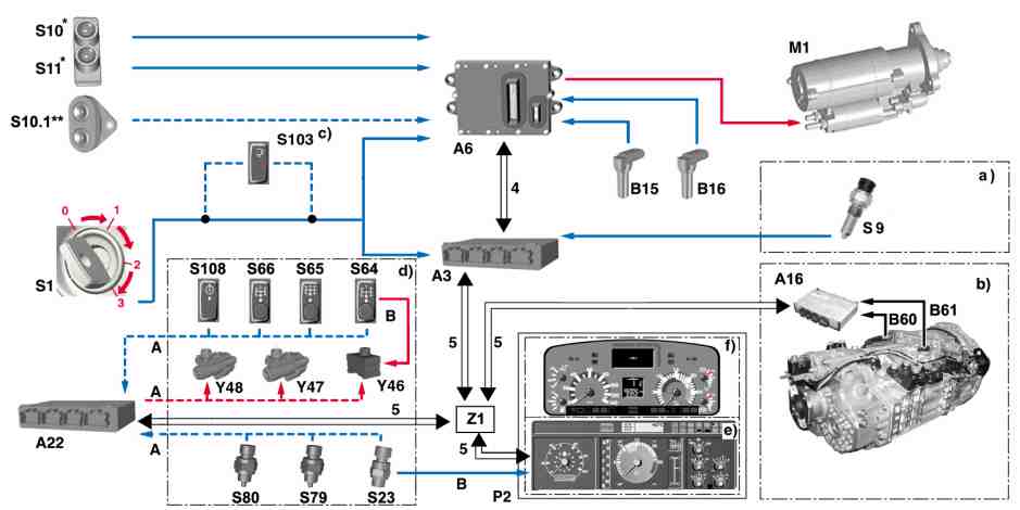
W15.30-1023-79
0 Ignition OFF
1 C. 15R ON
2 Circuit 15 ON
3 Kl.50
4 Engine CAN bus
5 Vehicle CAN bus
A3 Drive control (FR) control unit
A6 MR/PLN control unit
A16 GS/EPS control unit
A22 PSM control unit
- Only for vehicles with code (ED5) parameterizable special module (PSM), code (EM7) parameterizable special module with body CAN bus or code (EM8) parameterizable special module with body and trailer CAN bus
B15 Crankshaft angle position sensor
B16 Cylinder 1 TDC sensor
B60 Gear sensor
a) Vehicles with code (GS1) Gearshift "mechanical" or code (GS3) Gearshift "hydraulic"
b) Vehicles with code (GS2) Gear control
c) For vehicle with a tail lift
d) On models fitted with PTO.
e) up to 31.12.1999
f) as of 01.01.2000
* Engine 541.9 up to engine end no. 106266 and engine 542.9 up to engine end no. 109389
** Engine 541.9 as of engine end no. 106267 and engine 542.9
as of engine end no. 109390
B61 Gate sensor
M1 Starter
P2 Instrument
S1 Drive switch
S9 Neutral position switch
S10 Pushbutton switch Start engine
S10.1 Pushbutton switch Start engine/Stop engine
S11 Pushbutton switch Stop engine
S23 PTO 1 indicator switch
S64 PTO 1 switch
S65 PTO 2 switch
S66 PTO 3 switch
S79 PTO 2 indicator switch
S80 PTO 3 indicator switch
S103 Cargo lift gate switch
S108 Switch, ADR
Y46 PTO 1 solenoid valve
Y47 PTO 2 solenoid valve
Y48 PTO 3 solenoid valve
Z1 CAN star point cab dash support
A Vehicles with code (ED5) parameterizable special module (PSM),
code (EM7) parameterizable special module with body CAN bus or
code (EM8) parameterizable special module with body and trailer CAN bus
B Vehicles without
code (ED5) parameterizable special module (PSM),
code (EM7) parameterizable special module with body CAN bus or
code (EM8) parameterizable special module with body and trailer CAN bus
General information
Actuation of the starter (M1) takes place exclusively over the circuit 50 output on the MR/PLN control unit (A6).
This allows
protection of the starter against mechanical and thermal overloading (start time limitation, overspeed limiting device)
with the aid of the STAR DIAGNOSIS, to conduct active diagnosis based on a compression pressure comparison measurement
Because the starter output stage on the MR/PLN control unit (A6) does not deliver sufficient current or is not designed for high currents (the starter output stage switches off at a maximum current of 3 A at 0°C or 2 A at 25°C) there is a front-end relay between the control unit and the starter solenoid for the starter (M1).
Actuation of the starter (M1) takes place
if the circuit 50 signal from the drive switch (S1) is detected at the input by the MR/PLN control unit (A6)
for a start command from the PSM control unit (A22), in as far as the vehicle is fitted with code (ED5) parameterizable special module (PSM), code (EM7) parameterizable special module with body CAN bus or code (EM8) parameterizable special module with body and trailer CAN bus
-----------------------------------------------------------------------------------------
on engine 541.9 up to engine end no. 106266 and engine 542.9 up to engine end no. 109389:
by actuating the pushbutton switch Start engine (S10) or for simultaneous actuation of the pushbutton switch Start engine (S10) and pushbutton switch Stop engine (S11)
on engine 541.9 as of engine end no. 106267 and engine 542.9 as of engine end no. 109390:
by actuating the starter switch on the pushbutton switch Start engine/Stop engine (S10.1) or for simultaneous actuation of the start and stop switch on the pushbutton switch Start engine/Stop engine (S10.1).
For safety reasons, the starter (M1) is also actuated in the case where no valid transponder code has been recognized in the MR/PLN control unit (A6).
-----------------------------------------------------------------------------------------
Requirements
Voltage supply (circuit 30 and circuit 15) applied to MR/PLN control unit (A6)
Lock on starter operation lifted, which means:
Transmission in neutral (only required for a start command over the pushbutton switch Start engine (S10) or over the starter switch on the pushbutton switch Start engine/Stop engine (S10.1), since a start command over the drive switch (S1) must be achieved under all conditions)
Power take-off, where installed, switched off
Engine stationary or engine speed <50 rpm
Prerequisites for lifting the lock on the starter operation are checked by the drive control (FR) control unit (A3). If all requirements are fulfilled, it transmits an appropriate message over the engine CAN bus (4) for start enable to the MR/PLN control unit (A6) which then actuates the starter (M1).
Thus if there is a start command the drive control (FR) control unit (A3) will first check the following points before it can issue the start enable:
-----------------------------------------------------------------------------------------
Transmission position "N"
for vehicles with code (GS1) Gearshift "mechanical" or code (GS3) Gearshift "hydraulic" (a)
The shift signals from the switch for Neutral (S9) are evaluated to determine the transmission position "N". The switch for Neutral (S9) is connected to the drive control (FR) control unit (A3) which detects and analyses the applied position.
for vehicles with code (GS2) Gear control (b)
The current applied position in the transmission is determined by the transmission control/electronic power shift control unit (A16). Here it analyzes information from the gear sensor (B60) and the gate sensor (B61), converts these into an appropriate message and transmits this over the vehicle CAN bus (5) to the drive control (FR) control unit (A3).
-----------------------------------------------------------------------------------------
Engine speed
The engine speed determined by the MR/PLN control unit (A6) passes over the engine CAN bus (4) to the drive control (FR) control unit (A3).
It is transmitted by the drive control (FR) control unit (A3) on the one hand over the vehicle CAN bus (5) to the instrument (P2) and on the other hand is used for checking the requirements and the associated start enable
Operating condition of the power take-off or the power take-offs depending on the vehicle equipment
The operating condition of the power take-off (or the power take-offs depending on the vehicle equipment) is determined over the indicator switch for power take-off 1 (S23), power take-off 2 (S79) and possibly also power take-off 3 (S80).
The applied positions of the indicator switch for power take-off 2 (S79) and power take-off 3 (S80) are exclusively detected by the PSM control unit (A22) while the applied positions of the indicator switch for power take-off 1 (S23), depending on the vehicle equipment, are either detected by the PSM control unit (A22) or the instrument (P2).
-----------------------------------------------------------------------------------------
Both the instrument (P2) and the PSM control unit (A22) transmit the switching condition of the power take-offs over the vehicle CAN bus (5) to the drive control (FR) control unit (A3).
Functional sequences
1 Actuation of the starter (M1) for a start command over the drive switch (S1)
On vehicles with tail lift (c), the
circuit 50 signal line is interrupted as soon as the switch tail lift (S103) is actuated. Actuation of the starter (M1) can only be achieved if the switch for the tail lift (S103) is in the starting position.
After switching on the ignition (circuit 15) and turning the ignition key into the engine start position (position circuit 50 (3)), the circuit 50 signal from the drive switch (S1) passes simultaneously to the drive control (FR) control unit (A3) and the MR/PLN control unit (A6).
-----------------------------------------------------------------------------------------
The drive control (FR) control unit (A3) transmits a message as a start command as soon as it is applied to the control unit input circuit 50 to the MR/PLN control unit (A6) over the engine CAN bus (4) which compares this with the directly incoming circuit 50 signal from the drive switch (S1) (consistency testing):
If the circuit 50 signal is applied to the MR/PLN control unit (A6) without the message from the drive control (FR) control unit (A3) being sent then the fault "Terminal 50 inconsistent" will be stored in the diagnostic fault code memory after 1 second and the start will be delayed by this period of time. This redundancy allows, for example, for failure of the CAN bus system, that the vehicle can still be started over circuit 50 and that it can be driven at a fixed specified engine speed to next workshop, if a correct transponder code has been recognized.
If the MR/PLN control unit (A6) receives the circuit 50 signal simultaneously over the circuit 50 connection on the control unit input and over the engine CAN bus (4) then this immediately actuates the starter (M1) (without delay).
Actuation of the starter (M1) takes place until the start command is retracted, the engine reaches
-----------------------------------------------------------------------------------------
the starter cut-off speed (about 450 rpm for a warm engine through to about 650 rpm for a cold engine) or the maximum start time of 40 seconds has been exceeded (start time limitation).
If a compression pressure comparison measurement is made with the aid of STAR DIAGNOSIS then this breaks off the MR/PLN control unit (A6) after a certain time as well as actuation of the starter (M1).
The compression pressure comparison measurement is based on the fact that the piston on a cylinder with a poorer compression turns past ignition TDC faster than a cylinder with good compression. It is also exactly at this point in time that slight engine speed fluctuations occur which the MR/PLN control unit (A6) can detect on the basis of rpm signals from the crankshaft angle position sensor (B15) and the TDC sensor on cylinder 1 (B16). It calculates deviations between the individual cylinders and passes these on to the STAR DIAGNOSIS where they are indicated as % comparative values. In order to obtain the most accurate possible values for the compression pressure comparison measurement, starting of the engine is prevented in that the solenoid valves in the unit pumps are not actuated.
-----------------------------------------------------------------------------------------
2 Actuation of the starter (M1) for a start command from the PSM control unit (A22)
Only for vehicles with code (ED5) parameterizable special module (PSM), code (EM7) parameterizable special module with body CAN bus or code (EM8) parameterizable special module with body and trailer CAN bus.
The PSM control unit (A22) is networked over the vehicle CAN bus (5) with the drive control (FR) control unit (A3). As soon as an appropriate message concerning a start demand is transmitted, the drive control (FR) control unit checks (A3) the conditions and, if they are met, passes on the start demand together with the start enable with appropriate messages to the MR/PLN control unit (A6). The MR/PLN control unit (A6) actuates the starter (M1) until the start demand is retracted by the PSM control unit (A22), the starter cut-off speed is reached (about 450 rpm for a warm engine through to about 650 rpm for a cold engine) or actuation of the starter (M1) is interrupted to protect against
-----------------------------------------------------------------------------------------
mechanical or thermal overload (start time limitation).
3 Actuation of the starter (M1) for a start command over the pushbutton switch Start engine (S10) or over the starter switch on the pushbutton switch Start engine/Stop engine (S10.1)
The applied positions of the pushbutton switch Start engine (S10) or the pushbutton switch Start engine/Stop engine (S10.1) are evaluated by the MR/PLN control unit (A6) If the pushbutton switch Start engine (S10) or the starter switch on the pushbutton switch Start engine/Stop engine (S10.1) is actuated, it sends a message to the MR/PLN control unit (A6) over the engine CAN bus (4) concerning the start command at the drive control (FR) control unit (A3).
The drive control (FR) control unit (A3) checks the reliability, that is the conditions for lifting the block on the starter operation must be fulfilled, and gives the start enable, if all conditions are met, by transmitting an appropriate message.
-----------------------------------------------------------------------------------------
On receiving this message, the MR/PLN control unit (A6) actuates the starter (M1) until the pushbutton switch Start engine (S10) or the starter switch on the pushbutton switch Start engine/Stop engine (S10.1) is released again, the starter cut-off speed is reached (about 450 rpm for a warm engine through to about 650 rpm for a cold engine) or actuation is broken off autonomously to protect against mechanical or thermal overload (start time limitation).
4 Actuation of the starter (M1) for simultaneous actuation of the pushbutton switch Start engine (S10) and the pushbutton switch Stop engine (S11) or simultaneous actuation of the start and stop switches on the pushbutton switch Start engine/Stop engine (S10.1)
This usability is used to allow the engine to be cranked for service work without starting.
-----------------------------------------------------------------------------------------
The MR/PLN control unit (A6) actuates the starter () but prevents actuation of the solenoid valves in the unit pumps as soon as it recognizes that
for engine 541.9 up to engine end no. 106266 and
engine 542.9 up to engine end no. 109389:
the pushbutton switch Start engine (S10) and the pushbutton switch Stop engine (S11)
for engine 541.9 as of engine end no. 106267 and
engine 542.9 as of engine end no. 109390:
the start and stop switches on the pushbutton switch Start engine/Stop engine (S10.1)
M1have been actuated simultaneously.
This prevents injection so the engine does not start.
Also here actuation of the starter (M1) only occurs if all conditions are met and the start enable is issued by the drive control (FR) control unit (A3).
-----------------------------------------------------------------------------------------
For safety reasons the signal which initiated a start must always be retracted again before a new start is possible on the basis of the same signal (start locking).
If the starter (M1) was actuated
by actuation the pushbutton switch Start engine (S10),
by actuation of the starter switch on pushbutton switch Start engine/Stop engine (S10.1),
by simultaneously pressing the pushbutton switch Start engine (S10) and the pushbutton switch Stop engine (S11) or
by simultaneously pressing the start and stop switch on the pushbutton switch Start engine/Stop engine (S10.1)
an engine start is only possible for safety reasons over the drive switch (S1) after the ignition has been switched off and switched on again.
Crankshaft angle position sensor - location/task/design/function | |||
Cylinder 1 TDC sensor - location/task/design/function | |||
MR/PLN control unit - location/task | |||
Pushbutton switch Start engine - location/task | Engine 541.9 up to engine end no. 106266 | ||
Pushbutton switch Engine stop - location/task | Engine 541.9 up to engine end no. 106266 | ||
Pushbutton switch Engine start/Engine stop - location/task | Engine 541.9 as of engine end no. | ||
Neutral switch - location/function | Vehicles without code (GS2) Gear control | ||
Transmission control/electronic power shift control unit - location/task | Vehicles with code (GS2) Gear control | ||
Gate sensor - location/task | Vehicles with code (GS2) Gear control | ||
Gear sensor - location/task | Vehicles with code (GS2) Gear control | ||
Indicator switch for power take-off 1 - location/task | Vehicles with at least 1 power take-off | ||
Indicator switch for power take-off 2 - location/task | Vehicles with at least 2 power take-offs | ||
Indicator switch for power take-off 3 - location/task | Vehicles with at least 3 power take-offs | ||
Drive control (FR) control unit - location/task | |||
Parameterizable special module control unit - location/task/body | Only for vehicles with code | ||
Switch for power take-off 1 - location/task | Vehicles with at least 1 power take-off | ||
Switch for power take-off 2 - location/task | Vehicles with at least 2 power take-offs | ||
Switch for power take-off 3 - location/task | Vehicles with at least 3 power take-offs | ||
Switch for working speed control - location/task | |||
Switch for tail lift - location/task | Only model 950 with tail lift |