Pneumatic brake system |
Number | Designation | Chassis 368.00/05/10/11/15; 382.07/08/11/12/15/17/18; 384.06/07/11/14/20/22/31/33; 634.001/011/012/014/061/071/081; 693.02/10/12/14/15/17/18/19/34/38; 694.00/02/04; 695.01/02/03/04/05; 695.30; 696.08/09; 696.36 | Chassis 364, 384.08/09, 386, 388, 397, 660, 664, 682, 688 | ||
BE42.60-B-1001-01A | Pressure regulator | Opening pressure - Wabco/Knorr | bar | 9,8 ... 10,2 | 7,9 ... 8,3 |
Closing pressure - Wabco/Knorr | bar | 8,7 ... 9,3 | 6,9 ... 7,7 | ||
Service pressure - Wabco/Knorr | bar | 13 | 12 | ||
Opening pressure of safety valve - Wabco/Knorr | bar | 14,5 ... 17,0 | 12,0 ... 15,0 | ||
Tires filling safety valve opening pressure - Wabco | bar | - | 9,0 ... 13,0 | ||
Admissible leakage - Wabco/Knorr | bar (menor ou igual cm3) | 10 | 10 | ||
Pressure on the test stand feeding circuit - Wabco/Knorr | bar | 15 | 10 | ||
Pressure applied to the port 1 for leak test - Wabco/Knorr | bar | 10 | 7 | ||
Pressure applied on the port 21 for leak test - Wabco/Knorr | bar | 10 | 7 |
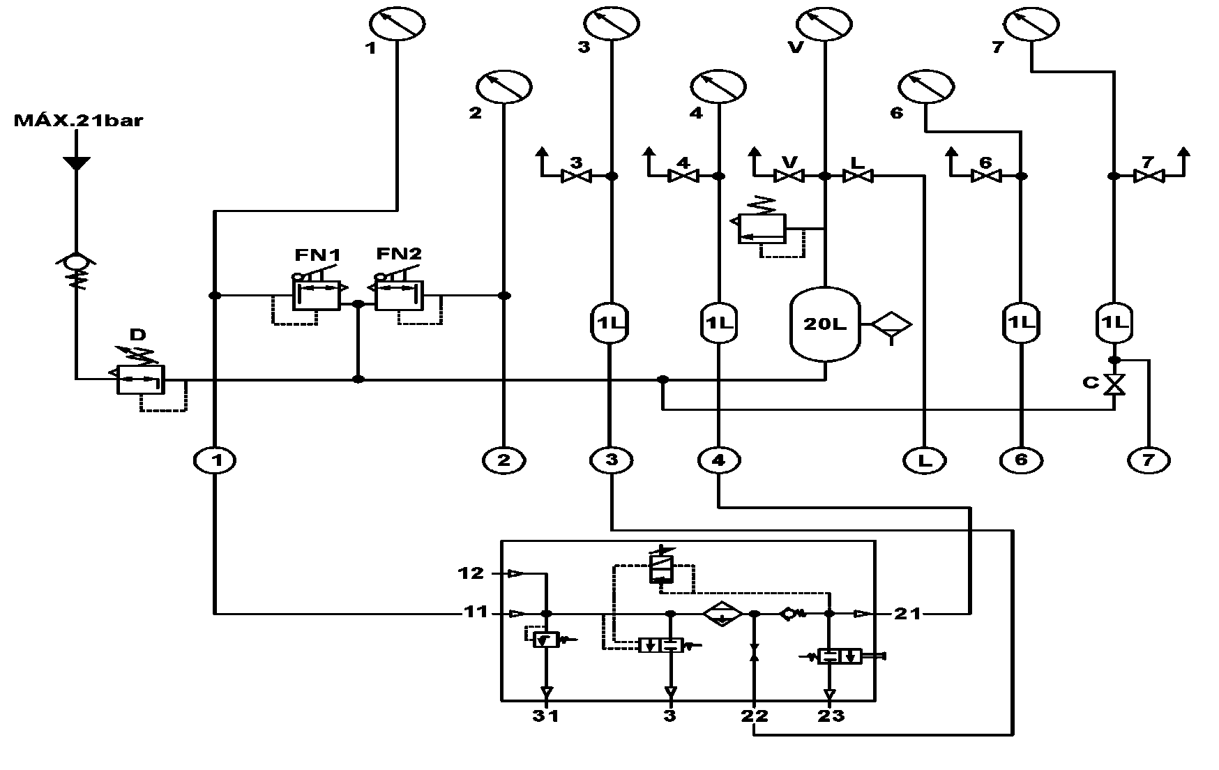
1 - Test stand accessories
D = Pressure reducing valve
FN1= Pressure regulating valve (fine adjustment) with discharge to atmosphere
V = Indicator manometer of the stand supply pressure
1; 3; 4 = Pressure indicating manometers with 0.1 bar divisions, capacity going up to 16 bar
1L = Air reservoir with 1 liter capacity
20L = Air reservoir with 20 liter capacity
C; V; 3; 4 = Stopcocks (taps)
(1); (3); (4) = Quick clamping device connections on the stand
2 - Visual check
Check the air drier and pressure regulator regarding the outer damages.
3 - Necessary devices
Connection assembly adapter in gantry 21 of the air drier.
4 - Prepare the installation of air drier in tests stand
Disassemble the air drier from four-circuit protection valve.
Remove the mounting support from Air Processing Unit, located in the air drier.
5 - Install the air drier in stand
Connect quick clamping device (1) of the test stand at gate 11 of the air drier.
Connect quick clamping device (3) of the test stand at gate 22 of the air drier.
Connect quick clamping device (4) of the test stand at gate 21 of the air drier.
B42.60-0220-12

6 - Prepare for the test
Tighten the pressure regulating valve screw until press the spring completely.
Fully tighten the spring seat (4-hole nut) of the safety valve.
Actuate and disable the valve FN1 many times (test stand) to ensure the valve components settlement.
7 - Test for tightness
Actuate valve FN1 until manometer (1) indicates 10 bar.
Use neutral soap foam around the filter seal, pressure regulating valve cover and pressure regulating valve discharge guide.
If air bubbles are observed in the foam, disassemble the valve and check: the correct assembly procedure; dirt on valve seating areas and piston movement; need to replace damaged parts including valve body.
Close valve FN1 until manometer 1 indicates "zero" bar.
8 - Test the safety valve working and adjust it
Actuate valve FN1 until manometer 1 indicates 14,5 bar .
Release slowly spring seat (4-hole nut) of the safety valve until releasing the air in the drier.
Disable valve FN1 until the manometers 1 and 3 indicate 0 (zero) bar and the manometer 4 indicates 4.5 bar (maximum reduction of pressure 3 bar).
Open the tap 4 until the manometer 4 indicates "zero" bar and then close it again.
If manometer 4 shows a pressure reduction higher than 3 bar, check: the sealing ring of the check valve (gate 21 of the air drier), the diaphragm and adjustment screw valve of the pressure adjuster, dirty around body seal and pistons movement.
9 - Test the pressure regulating valve opening and closing (vehicles 382, 693, 694, 695, and 696)
Actuate valve FN1 until manometer 1 indicates 13 bar.
Slowly loosen the pressure regulating valve adjustment screw until the air is released.
Manometer 4 will indicate a pressure of 13 bar.
Slowly open the side tap 4 (test stand) until you notice that the pressure indicated on the manometer 4 begins to decrease.
Keeping tap 4 in this position, the pressure indicated on the manometer 4 will decrease to 11.2 to 11.7 bar and then increase to 13 bar.
Release the pressure regulating valve adjustment screw until the manometer 4 indicates pressure at 10 bar.
Indicated pressure on manometer 4 will decrease to 9.4 to 8.7 bar and then increase up to 10 bar.
If the reduction of pressure indicated on the manometer 4 drops below 8.7 bar, remove the spring wedges which is located in the discharge guide of the air drier. If the reduction of pressure is above 9.4 bar, add wedges.
Do it again.
In vehicles 664.231/.238/.239 and 688.276 observe the adjustment values.
10 - Remove the air drier and pressure regulator from tests stand
Depressurize the air drier circuits and adjuster and disconnect the quick clamping devices of the test stand.
Protect the valve gantries with suitable plastic covers.
B42.60-0194-02