Front axle brake caliper
Número | Denominação | Front axle 739.395/397/398 | |||
BA42.10-B-1002-10A | Caliper support bolts in the axle | M16X1.5 | Nm | 260 | |
BA42.10-B-1003-10A | Brake caliper main body attachment bolt (assembled) in the front axle | Hydro-vacuum brake | M12x1.5 | Nm | - |
Pneumatic brake | M16x1.5 - first stage | Nm | 260 | ||
M16x1.5 - second stage | degrees | - | |||
Pneumatic brake | M18x1.5 | Nm | - | ||
Rear axle brake caliper
Número | Denominação | Rear axle 740.698/752; 746.971/973 | |||
BA42.10-B-1001-12D | Brake caliper bolt | first state | M16 X 1.5 - Normal and micro encapsulated thread | Nm | 180 |
second stage | degrees | 90 | |||


055 589 02 61 00
Mandrel
055 589 04 61 00
Ancillary device
Produtos para reparos
Número | Denominação | Número de pedido |
BR00.45-B-1013-06A | Renolit HLT2 grease, white color (contains mineral oil) | Knorr II14525 |

B42.10-0356-03
Fixed bearing (bronze sleeve) in the SN 7000 brake:
To install the guard and guide pin (5), following the work steps 1 to 4:
1 Lubricate the bronze sleeve (7) and the guide pin (5) with the specified grease.
2 Fit the new guide pin (5) inside the bronze sleeve (7).
3 Insert the sealing lip (9.1) of the internal seal guard (9) in the guide pin housing (5), then fit the protective ring (58) on the sealing lip.
4 Compressing the assembly should not build internal pressure in the inner fanfold guard (9) at the point indicated by the arrow (second smallest frame on the left).

B42.10-0421-03
To install the metal cover (10b) next to bronze sleeve side (7) on the SN7000 clamp, follow the work steps 5 to 7:
5 Move the holder (2) and place the shim so that the assembly remains in this position.
6 Place the new metal cover (10b) in the guide pin housing (5).
7 Assemble by using the tools (K5) with (K6) and a hammer.
The metal cover (10b) should not be installed without compressing the sealing fanfold guard (9). This procedure is intended to remove the internal pressure, thus improving the durability of the pads and the service life of the internal fanfold guards (9).
B42.10-0356-03
Floating bearing on the SN 7000 brake caliper at the front axle of the O500 vehicles:
To install the guide pin on the side of the Type-2 rubber sleeve (6a) follow the work steps 8 and 9:
8 Lubricate the rubber sleeve (6a) and guide pin (4a) with the specified grease.
9 Mount the new guide pin (4a) inside the rubber sleeve (6a).
The Type-2 rubber sleeve (6a) used for the SN7000 calipers is applied only to the front axle of O500 vehicles. All other SN7000 calipers use DU-Type sleeves (6b).

B42.10-0297-03
To install the holder on the SN7000 brake caliper using a Type-2 rubber sleeve (6a), follow the work steps 10 and 11:
10 Place the holder (2) of the brake caliper (1) on the guide pins and push the holder to compress the inner fanfold guard. No internal pressure should be built in the guard.
For SN7000 calipers, the screw (40) (indicated by the arrow) with the micro-encapsulated thread is applied to the bronze sleeve side. At the opposite side of the Type-D sleeve, the screw (39) with a regular thread is applied. The tightening torque of both screws is identical. Both screws (39) and (40) can only be used once.
11 Install and evenly tighten stepwise the new screws to the specified torque.
B42.10-0420-03
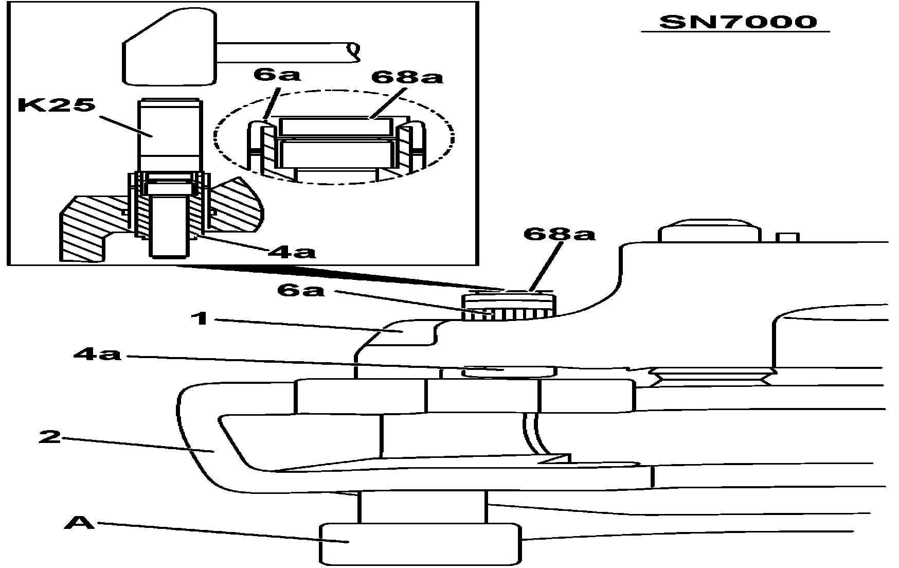
To install the metal cover (68a) with the Type-2 rubber sleeve (6a), follow the work steps 12 to 14:
12 Move the holder (2) and place the shim (A) so that the assembly formed with the caliper (1) remains in this position.
13 Place the new metal cover (68a) on guide pin housing (4a).
14 Assemble using the tools (K25) and a hammer.
B42.10-0297-03
Floating bearing on the SN 7000 brake caliper, except at the front axle of O500 vehicles:
To install the guide pin on the side of the DU-type sleeve (6b), follow the work steps 15 to 17:
15 Lubricate the DU sleeve (6b) and the guide pin (4b) with the specified grease.
16 Fit the new guide pin (4b) inside the DU sleeve (6b).
17 Fit the sealing lip (9.1) of the internal sealing fanfold guard (9) in the guide pin housing (4b), then fit the protective ring (58) on the sealing lip.

B42.10-0357-03
To install the holder on the SN7000 caliper using the DU sleeve (6b), follow the work steps 18 to 20:
18 Place the guide pins (5) and (4b) and push the holder so as to compress the internal fanfold guards (9).
19 During the operation, no internal pressure should be found in the fanfold guards (9).
For SN7000 calipers, the screw (40) (indicated by the arrow) with the micro-encapsulated thread is applied to the bronze sleeve side. At the opposite side of the Type-D sleeve, the screw (39) with a regular thread is applied. The tightening torque of both screws is identical. Both screws (39) and (40) can only be used once.
20 Install and evenly tighten stepwise the new screws to the specified torque.
To install the metal cover (68b) on the SN7000 caliper with the DU sleeve (6b), follow the work steps 21 to 23:
21 Move the holder (2) and place the shim so that the assembly remains in this position.
22 Place the new metal cover (68b) in the guide pin housing (4).
23 Assemble by using the tools (K5) with (K23) and a hammer.
The metal cover (68b) should not be installed without compressing the sealing fanfold guard (9). This procedure is intended to remove the internal pressure, thus improving the durability of the pads and the service life of the internal fanfold guards (9).