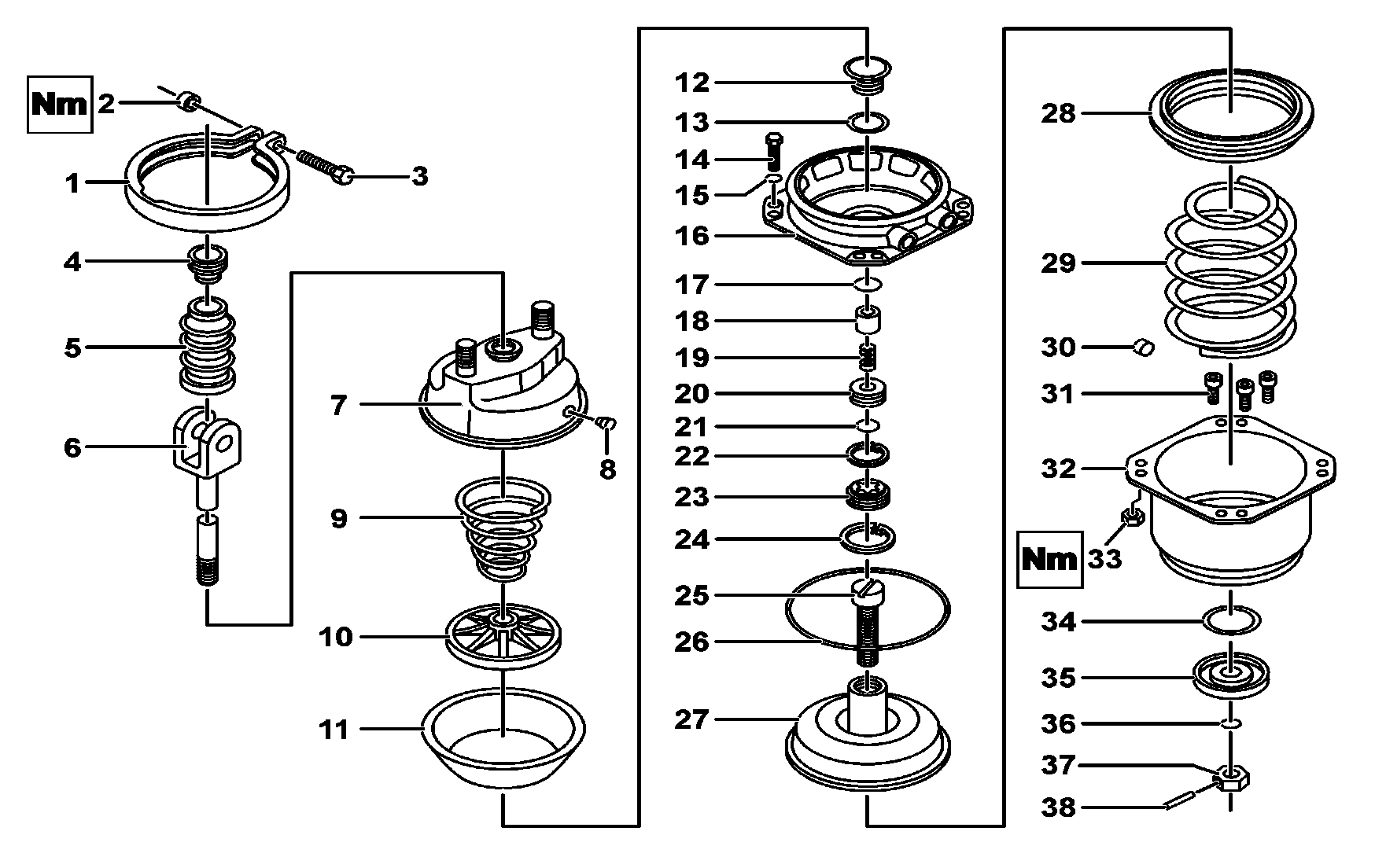
1 | Belt |
2 | Nut |
3 | Bolt |
4 | Ring |
5 | Cup |
6 | Forked rod |
7 | Cylinder |
8 | Cover |
9 | Spring |
10 | Piston |
11 | Diaphragm |
12 | Thrust part |
13 | Seal ring |
14 | Bolt |
15 | Washer |
16 | Intermediate flange |
17 | Seal ring |
18 | Piston |
19 | Spring |
20 | Cover |
21 | Seal ring |
22 | Lock-ring |
23 | Sealant |
24 | Lock-ring |
25 | Relief bolt |
26 | Seal ring |
27 | Piston |
28 | Gasket |
29 | Spring |
30 | Covering |
31 | Bolt |
32 | Cylinder |
33 | Nut |
34 | Seal ring |
35 | Cover |
36 | Seal ring |
37 | Nut |
38 | Locking pin |
B42.10-0320-06
| Disassemble | ||
Warning | Risk of injury caused by pinching or crushing when working on springs or spring bodies that are under tension | Use only approved tensioning devices; additionally screen off hazardous area if necessary. Check special tools for damage and proper operation (visual inspection). Wear protective gloves. | |
1 | Gently compress the cylinder, releasing the nut (2) from the clamping strap (1) screw (3) | This information addresses the disassembly and assembly of Knorr and Wabco brand combination cylinders, since both are similar. Minor differences are specified in the text. | |
Use a press with a suitable base. | |||
2 | Relieve the pressure from the press and separate the membrane cylinder portion from the spring storage part and remove the diaphragm (11) | Due to the different mounting positions of the components from a single combination cylinder, pre-marking the spring accumulator cylinder, the intermediate flange, the diaphragm cylinder and the clamping strap against the assembly is recommended. | |
3 | Disassemble the diaphragm cylinder components | In the Wabco combination cylinder, the forked rod (6) and the piston (10) form a single piece, whereas in Knorr the plunger is screwed to the forked rod. | |
4 | Secure the combination cylinder by the intermediate flange (16) and loosen the relief screw (25) to approximately half of its total stroke | ||
5 | Remove the thrust piston (12) | In the Wabco combination cylinder, remove the thrust piston (12) with the aid of screwdrivers, while in Knorr, fasten the plunger to a vise with aluminum jaws and unscrew it by manually turning the cylinder. | |
6 | Remove the locking pin (38) and loosen the nut (37) from the relief screw (25) | ||
7 | Completely loosen the relief screw (25) and remove it | For Knorr cylinders, use an appropriate screwdriver. | |
8 | Disassemble the spring accumulator portion by slightly compressing it, loosen the nuts (33) from the fastening screws (14) from the intermediate flange (16) | Leave a retraction stroke in the press spindle to allow the spring distension. | |
9 | Disassemble the venting valve components (17, 18, 19, 20, 21, 22) mounted inside the thrust part (12) | For the Knorr combination cylinder. | |
10 | Remove the lock ring (24) and extract the sealant (23) | For the Knorr combination cylinder. | |
Drift | |||
| Clean | ||
11 | Clean the parts and inspect for wear or damage; if necessary, replace them | Use a suitable product to prevent damage to the rubber and plastic parts of the component. | |
| Assemble | ||
12 | Mount the intermediate flange (16) | The repair kit parts should be replaced at each disassembly. | |
For Knorr cylinders, insert the sealant (23) by using a suitable mandrel and install the lock rings (22) and (24). | |||
For Wabco cylinders mount the sealing ring (17) on the intermediate flange (16). | |||
Drift | |||
13 | Mount the sealing ring (26) on the intermediate flange (16) | ||
14 | Mount the cover (30) on the spring (29) | ||
15 | Mount the gasket (28) on the Piston (27) | For Wabco cylinders, mount the guide ring on the piston (27). | |
16 | Mount the piston (27) on the intermediate flange (16). On the piston, install the spring (29) and cylinder (32), note the marks made when disassembling | Lubricate the piston spindle (27), the gasket (28), the cylinder walls (32) and the sealant (23) with grease. | |
Grease, DB supply specification 6804 - Class 267.0 | |||
17 | Compress the spring (29) to the cylinder edge (32), touch the intermediate flange (16) and insert the screws (14) with washers (15) and nuts (33) | .Intermediate flange attachment | |
18 | Lubricate the thread of the relief screw (25) with grease and screw it to half the full length | For Knorr cylinders, use a suitable screwdriver. | |
Grease, DB supply specification 6804 - Class 267.0 | |||
19 | Mount the sealing ring (36) on the end of the relief screw (25) and screw the nut (37) until perfect matching with the holes drilled, and place the locking pin (38) | For Knorr cylinders, the lock pin (38) opening should be perpendicular to the axis of the relief screw (25). | |
20 | Mount the components of the venting valve (17, 18, 19, 20, 21) on the thrust part (12) | ||
21 | Screw the thrust part (12) to the piston spindle (27) | Use aluminum jaws to prevent damage to the thrust part. | |
For Knorr-cylinders, apply a chemical lock to the thrust part (12) thread. | |||
Auto Lock | |||
22 | Install the sealing ring (13) on the thrust part (12) and mount it on the piston spindle (27) | Wabco cylinders. | |
23 | Completely screw the release screw (25) through the nut (37) | If possible, pressurize the cylinder through the connection (12). | |
Observe the maximum prescribed torque. | |||
.Spring relief bolt - maximum | |||
24 | Mount the spring (9), the cylinder (7), the hood (5) and the ring (4) on the forked rod (6) | In Knorr cylinders, the piston (10) is threaded to the forked rod (6), and removing it is necessary only for the replacement of parts. | |
Mount all three caps (8) on the cylinder; note the mounting position, since the bottom hole should remain open. | |||
25 | Mount the diaphragm (11) and the spring accumulator on the piston (10), note the marking made during disassembly | Compress the parts and place the strap (1), mount the screw (3) and apply the specified torque. Gently tap the edge of the strap in order to achieve settlement between the parts. | |
.Strap attachment | |||
26 | Mount the plastic compensation tube between the spring accumulator portion and the diaphragm cylinder | Wabco cylinders. | |
| Check | ||
27 | Install the combination cylinder on the bench and run the test | Check combination brake cylinder | |
Confirm the maximum stroke of the piston rod and the spring accumulator relief pressure. | |||
.Maximum stroke of cylinder piston | |||
.Relief pressure of the spring accumulator |

055 589 04 15 00
Drift
Odkazované dokumenty
- ar4210b002103a
- as0000z000101a Nebezpečí poranění přivřením nebo přiskřípnutím při pracích na předepnutých pružinách nebo tělesech pružin