Workshop equipment
WE58.40-Z-1001-15A | Chassis measuring instrument |
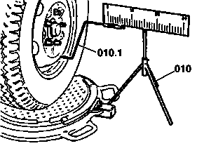
L40.20-0035-01
1 Place the measuring heads (010.1) of the adjustment stands (010) on the faces of the front rims on both sides so that they both are centered under the middle of the wheel.
The measuring heads of both adjustment stands must be set to the same length and same height.
2 Insert projectors into the projector brackets on the rear axle.

L40.20-0036-12
3 Align right projector to scale of measuring stand.
4 Align left projector to scale of adjustment stand.
5 Compare both measured values.
6 First determine the individual toe value by halving the difference between both measured values. Using the individual toe value and the associated wheelbase of the vehicle (e.g. 3350 mm) the angular alignment of the rear axle can be read off the "Toe angular alignment diagram" in angular minutes. Incorporate any lateral misalignment of the front axle and rear axle in the calculation, otherwise the value will be incorrect.
Example
displayed value on right 15
displayed value on left 13
Difference 2
Individual toe value 1
Value read off "Toe angular alignment diagram" for wheelbase of 3700 mm: approx. 9' 20".
If a difference is found, it may be an angular alignment of the rear axle or a lateral misalignment of the rear axle, caused by frame displacement.

L40.20-0001-06
Diagram for determining angular alignment of axles (optical measurement)
S Angular alignment in angular minutes
D Halved difference value at scale stands in cm
R Wheelbase in mm