Shift mechanism
Número | Denominação | Gearboxes 711.620/621/622 | |||
BE26.60-B-1001-01F | Reserve of synchronization | First and second speeds | inside cone | mm | 0,5 |
outside cone | mm | 0,5 | |||
Nominal measurement | mm | - | |||
Minimum measurement | mm | 1,00 | |||
Third, fourth and fifth speeds | Nominal measurement | mm | - | ||
Minimum measurement | mm | 0,5 | |||


D26.50-0094-01
D26.50-0089-01
Double-cone synchronizer (1st and 2nd gear)
A (synchronization supply, external cone)
1 Place synchronizer ring on a plate with flat surface.
2 Measure (measurement A) the synchronizer ring height with a depth gauges.


D26.50-0095-01
D26.50-0090-01
3 Place the outer cone on the flat surface plate.
4 Measure the height of the outer cone support surface (measurement B).
5 Add measurements A and B.


D26.50-0096-01
D26.50-0091-01
6 Place synchronizer ring in the outer cone so that it is parallel aligned.
7 Measure the C distance in at least 3 points and calculate the average value.
8 Calculate the synchronization supply of external cone (S) , S = C - (A+B) Compare the measurement S with the table. If the measurement is not obtained, replace the synchronization assembly with all parts.

D26.50-0092-01
B (synchronization supply, inner cone)
1 Place the synchronization ring on the gear and measure the height of the synchronizer ring upper edge until the gear (measurement C).

D26.50-0093-01
2 Remove the synchronizer ring, place the inner cone on gear and synchronizer ring as parallel as possible to the inner cone and press slightly.
3 Measure the upper edge height of the synchronizer ring to gear in at least 3 points and calculate the average measure (measurement D).
4 Calculate inner cone synchronization supply and compare it to the table. D - C = Inner cone synchronization supply.
In case you don't get the minimum synchronization supply values, replace synchronization assembly components.

D26.50-0097-01
C (total synchronization supply)
5 Place the inner cone, synchronizer ring and the outer cone on the gear, position them in parallel and press them slightly.
6 Check all synchronization supply perimeter with the feeler gauge between the outer cone and gear and calculate the average value.
Compare the value determined with the table, in case stipulated value is not achieved, replace the synchronization assembly.

D26.50-0098-01
7.1 Place the synchronizer ring on the synchronizer cone so that they are parallel aligned and press them slightly..
8.1 Check synchronization supply with a feeler gauge between the synchronizer ring in 5 or 6 points distributed in all perimeter and calculate the average value.
Compare the value determined with the table, in case stipulated value is not achieved, replace the synchronization assembly components.
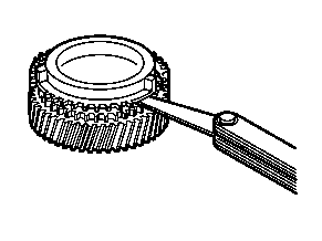
D26.50-1141-01
Simple synchronization
3rd, 4th and 5th gear synchronization supply
7.2 Place synchronizer ring on the 3rd position gear, perform the parallel alignment and press it down slightly.
8.2 Check synchronization supply with a feeler gauge between the synchronizer ring and the 3rd position gear in 5 or 6 points distributed in all perimeter and calculate the average value.
Compare the value determined with the table, in case stipulated value is not achieved, replace the synchronization assembly components.